
Silicon Carbide (SiC) Power Electronics for Advanced Power Quality
Third-generation SiC MOSFET platforms deliver >99% efficiency and higher power density for industrial active harmonic filter and reactive compensation systems.
3x–5x
Switching Frequency
40%
Energy Dissipation Cut
-30%
Footprint Volume
<1.2%
Full-Load Losses
Breaking the Silicon Limit — SiC MOSFET vs. Traditional Silicon IGBT
Modern semiconductor fabrication plants, hyper-scale data centers, and advanced automated manufacturing facilities impose demanding thermal and spatial constraints. Legacy silicon insulated-gate bipolar transistors (IGBTs) face definitive physical boundaries: tail currents, switching losses, and dynamic thermal dissipation restrict their capability in high-frequency active compensation topologies.
Silicon Carbide (SiC) wide bandgap semiconductor properties overcome these systemic barriers. By fundamentally eliminating reverse recovery charge constraints, SiC devices elevate switching speeds and minimize thermal dissipation. This generational transition enables industrial power quality equipment like the active harmonic filter to operate at peak efficiency with unprecedented volumetric power density.
Switching Frequency & Harmonic Mitigation
Carrier Bandwidth: 30 kHz to 60 kHz
SiC modules execute hard-switching between 30 kHz and 60 kHz with negligible cross-conduction. Conventional silicon IGBT switches remain constrained below 15 kHz to prevent destructive thermal runaway and excessive switching losses.
- · Eliminates legacy IGBT filtering blind spots beyond the 25th harmonic order.
- · Accurately mitigates up to the 50th harmonic order with minimal current ripple.
Conduction & Dynamic Switching Losses
Near-Zero Reverse Recovery Charge
Featuring unipolar conduction mechanisms, SiC MOSFETs exhibit near-zero reverse recovery charge. Inverter stage switching losses drop by 40% to 60% during intensive dynamic harmonic and reactive power compensation cycles.
- · Substantially reduces internal cabinet heat rise across fluctuating dynamic load profiles.
- · Full-load electrical conversion losses remain verified below 1.2%.
Thermal Kinetics & Temperature Endurance
3x Higher Thermal Conductivity
Silicon Carbide delivers 3x thermal conductivity compared to standard silicon. SiC dies withstand higher operating junction temperatures safely, sustaining rapid heat conduction to cold plates and heat sink assemblies.
- · Continuous full-rated output at ambient temperatures up to 55°C (131°F).
- · Eliminates thermal derating risks in enclosed, high-density industrial control rooms.
Power Density & Magnetic Downsizing
Volumetric Footprint Cut by 30% to 50%
Elevated carrier frequencies downscale passive components. Inductive filter chokes and DC-link capacitor assemblies shrink by over 40%, driving power density up to 3.2 kW/L.
- · Substantially reduces overall cubicle width, depth, and structural weight.
- · Preserves high-value white-space in cleanrooms, offshore platforms, and data halls.
Physics Comparison: Silicon vs. Silicon Carbide
The wide bandgap of Silicon Carbide (3.2 eV vs. 1.1 eV for silicon) produces a critical breakdown electric field nearly ten times greater than conventional silicon. This allows an ultra-thin, low-resistance drift layer capable of blocking thousands of volts while maintaining sub-microsecond switching responses.
Bandgap Energy
3.2 eV
vs. 1.1 eV (Silicon)
Breakdown Field
3.0 MV/cm
10x higher dielectric strength
Thermal Conductivity
4.9 W/m·K
3x faster heat dissipation

Engineering Comparison: Device-Level Parameters
Measured technical baseline comparing standard 400V industrial power quality assemblies under identical full-load conditions.
| Metric & Parameter | Standard Silicon IGBT System | iKonMac SiC MOSFET Architecture | Operational Impact |
|---|---|---|---|
| Carrier PWM Frequency | 10 kHz – 15 kHz | 30 kHz – 60 kHz | 3x to 4x bandwidth extension |
| Harmonic Mitigation Bandwidth | 2nd – 25th harmonic order | 2nd – 50th harmonic order | Zero high-order filtering blind spots |
| Full-Load Electrical Efficiency | 97.2% – 97.8% | ≥ 99.1% | Over 40% reduction in heat dissipation |
| Dynamic Step Response | < 5.0 ms | < 1.5 ms (full response) | Sub-cycle transient surge suppression |
| Volumetric Power Density | 1.8 kW / Liter | 3.2 kW / Liter | 30% to 50% cabinet footprint savings |
| Max Continuous Ambient Rating | 40°C (derated past 45°C) | 55°C (zero derating up to 45°C) | Eliminates supplemental cooling dependency |
Objective Engineering Selection Rationale
Silicon Carbide power electronics are engineered for demanding, high-efficiency environments rather than indiscriminately replacing mature silicon IGBT devices across routine applications. Standard silicon hardware remains cost-effective for non-critical municipal pumping stations and low-tier distribution substations where thermal boundaries, acoustic noise, and physical footprint are unconstrained.
Deploy SiC MOSFETs When:
Cleanroom floor area is at a premium, thermal chiller loads are strictly capped, or non-linear loads produce high-frequency switching distortion exceeding the 25th harmonic order.
Deploy Silicon IGBTs When:
Floor area is abundant, cooling overhead is unrestricted, and non-linear loads generate primarily standard 5th and 7th harmonic current components.
iKonMac Research & Design Support:
Backed by over 50 master and doctoral power electronics researchers, iKonMac designs proprietary active gate-driver protection circuits and low-inductance laminated busbars to maximize SiC switching reliability.
Silicon Carbide Power Electronics
Browse all Silicon Carbide power electronics products - SiC-based high-efficiency modules delivering >99% peak efficiency, reduced thermal loss, and compact footprints for mission-critical facilities.
Try removing one or more filters.
iKonMac Silicon Carbide Hardware Architecture and Product Scope
Third-generation wide-bandgap semiconductors redefine performance benchmarks across industrial electrical mitigation networks. By replacing legacy silicon insulated-gate bipolar transistors with Silicon Carbide (SiC) MOSFET architectures, iKonMac eliminates carrier storage delay, virtually removes diode reverse-recovery losses, and slashes switching dissipation. The resulting modular hardware portfolio delivers greater than 99% operational efficiency, unmatched volumetric power density, and elevated switching frequencies engineered specifically for mission-critical switchgear environments.
Manufactured at our advanced power electronics production facility, our equipment scope extends from sub-rack 19-inch slide-in drawers to high-capacity centralized floor-standing cubicles. Each standardized assembly integrates low-inductance planar busbars, multi-stage desaturation short-circuit protection, and isolated vertical cooling paths. This unified modular design enables facility managers, electrical contractors, and EPC engineers to deploy active harmonic filtering, dynamic static var generation, or integrated multi-parameter mitigation systems with seamless N+1 capacity redundancy.
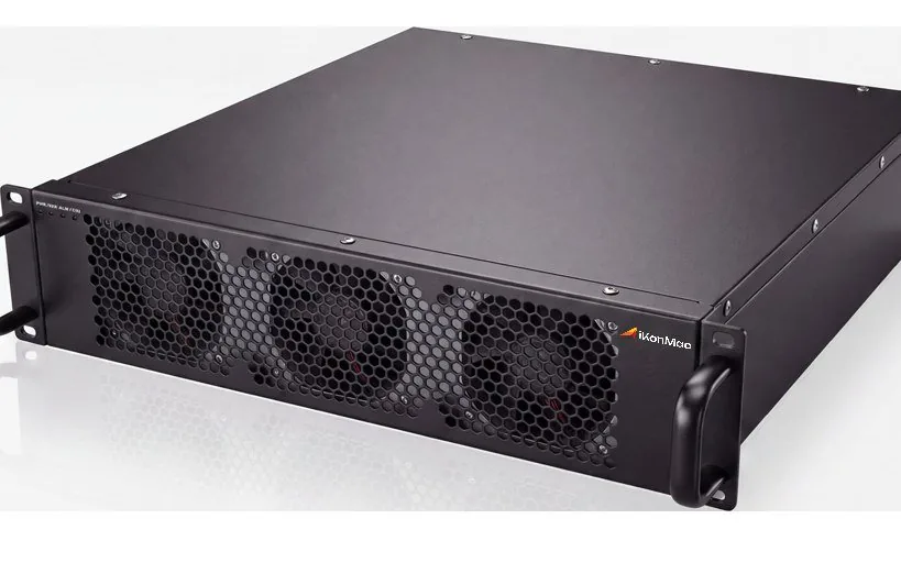
Modular SiC Active Harmonic Filter (SiC-AHF)
Engineered specifically for non-linear industrial distributions characterized by steep di/dt wavefronts and dense high-order harmonics. Operating at carrier switching frequencies up to 60 kHz, the SiC-AHF series cancels harmonic currents across variable frequency drives, uninterruptible power systems, and multi-pulse rectifier circuits.
Technical Ratings & Capabilities
- Current Output Ratings: Standardized 50A, 100A, and 150A slide-in drawer units, scalable in parallel up to 800A per standard cubicle.
- Harmonic Mitigation Scope: Full-spectrum mitigation from the 2nd through 50th harmonic orders with user-selectable individual order prioritization.
- Current Distortion Targets: Sustains total demand distortion (THDi) under 3% across dynamic, intermittent manufacturing load cycles.
- Switching Dynamic: Ultra-fast bridge topology minimizes high-frequency filter ripple, eliminating acoustic resonance in distribution networks.
Architecture Hierarchy: Review conventional silicon topologies via our standard Active Harmonic Filter line, or evaluate high-performance mission-critical installations through our Ultra Active Harmonic Filter series.
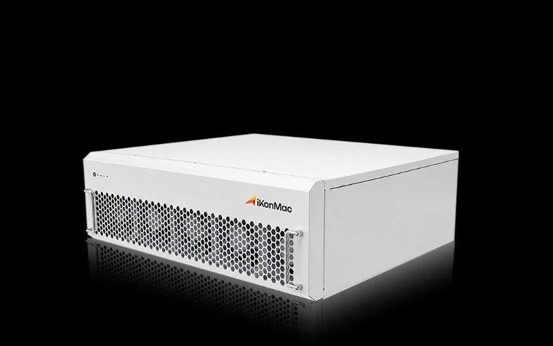
Modular SiC Static Var Generator (SiC-SVG)
Developed for rapid, continuously variable bidirectional reactive power control across highly automated manufacturing infrastructure. The SiC-SVG platform achieves sub-millisecond full-step responses while entirely preventing the resonance vulnerabilities of mechanical capacitor steps.
Technical Ratings & Capabilities
- Module Capacities: 50kvar and 100kvar ultra-compact chassis configurations optimized for low-profile industrial switchboard integration.
- Transient Response Time: Sub-millisecond instantaneous corrective step response with zero inrush current and clean zero-crossing tracking.
- Power Factor Regulation: Continuously targets and maintains displacement power factor at 0.99 or higher across inductive and capacitive regimes.
- Thermal Margin: Near-zero reverse-recovery switching loss supports minimal junction temperature rise during heavy cyclic motor surges.
Architecture Hierarchy: Explore baseline solid-state reactive equipment through the Static Var Compensator line, or analyze transmission-grade substations via our utility-scale High Voltage SVG portfolio.

Integrated SiC Hybrid System (SiC-HPQ)
A turn-key, pre-engineered floor-standing power quality system coordinating high-order harmonic cancellation, dynamic reactive support, and three-phase unbalance correction within an intelligent, centralized enclosure architecture.
Technical Ratings & Capabilities
- Bus Voltage Support: Available in 400V, 480V, and 690V industrial architectures with dual 50/60 Hz frequency auto-synchronization.
- Thermodynamic Airflow: Segregated cold-aisle intake and hot-air exhaust channels halve auxiliary HVAC power draw inside cleanrooms.
- Dynamic Multi-Mode Allocation: High-speed DSP control dynamically shifts inverter capacity between harmonic suppression and reactive power.
- Volumetric Power Density: Delivers 3.2 kW per liter volumetric density, reducing mechanical footprint up to 40% against IGBT cubicles.
Architecture Hierarchy: Discover our complete range of low-voltage and medium-voltage grid remediation hardware through the centralized Power Quality Products directory.
Cross-Series Engineering Specifications & Operational Matrix
The following parametric breakdown summarizes operational parameters and hardware performance boundaries across modular SiC active filters, static var units, and packaged system cubicles. All values reflect factory-calibrated bench measurements verified under continuous nominal electrical loading.
| Parameter Description | SiC-AHF Modular Series | SiC-SVG Modular Series | SiC-HPQ Complete Enclosure |
|---|---|---|---|
| Standard Bus Voltages | 400V / 480V / 690V (±15%) | 400V / 480V / 690V (±15%) | 400V through 690V Custom Build |
| Grid Operating Frequency | 50 Hz / 60 Hz (±5% Auto-Tracking) | 50 Hz / 60 Hz (±5% Auto-Tracking) | 50 Hz / 60 Hz (±5% Auto-Tracking) |
| Rated Operating Efficiency | ≥ 99.1% at Full Inverter Capacity | ≥ 99.3% at Full Inverter Capacity | ≥ 99.0% (Including Magnetics) |
| Harmonic Mitigation Range | 2nd to 50th Harmonic Orders | Selective 3rd, 5th, 7th Order Tuning | 2nd to 50th Harmonic Orders |
| Dynamic Response Velocity | < 1.5 ms Full Step Response | < 1.0 ms Fast Step Response | < 1.5 ms Unified Closed-Loop |
| Operating Temperature Limits | -10°C to +55°C (No Derating to 45°C) | -10°C to +55°C (No Derating to 45°C) | -10°C to +50°C (Dual-Zone Cooling) |
| Digital Telemetry Protocols | Modbus-RTU, Modbus-TCP, CANbus | Modbus-RTU, Modbus-TCP, CANbus | Modbus-TCP, IEC 61850, Dual Cloud I/O |
Industrial Manufacturing Rigor and Factory Validation
Supported by an annual delivery capacity exceeding 3.5 million Amperes and kvar, all iKonMac Silicon Carbide equipment undergoes stringent continuous quality screening. Units are built at our Shanghai manufacturing facility under rigorous ISO 9001 and ISO 14001 process controls.
Prior to dispatch, every modular drawer undergoes 100% full-load dynamic burn-in testing, high-frequency insulation dielectric validation, and thermographic load examination. This disciplined production framework supports continuous reliability across hyperscale computing centers, automated manufacturing, and heavy metallurgy substations worldwide.
Empirical Performance Benchmark — Measured Datasheet Specifications
Specifying electrical power quality equipment for high-availability industrial networks demands empirical, repeatable test data rather than generalized component claims. Shanghai iKonMac subjects every silicon carbide inverter topology to rigorous calorimetric loss validation, dynamic full-load step cycles, and calibrated temperature-rise logging inside accredited multi-megawatt testing bays.
The datasheet matrix below reflects synchronized bench testing comparing conventional silicon IGBT active harmonic filter platforms with third-generation Silicon Carbide (SiC) MOSFET hardware. Operating across identical 400V non-linear industrial load profiles, the SiC wide bandgap architecture establishes verifiable performance gains across continuous conversion efficiency, PWM carrier bandwidth, and thermal dissipation metrics.
45% operating loss reduction
Direct reduction in internal inverter-stage energy dissipation under continuous 100% rated compensation duty.
300% carrier frequency increase
Enables targeted mitigation of high-frequency harmonics up to the 50th order with minimal residual output ripple.
60% faster transient mitigation
Sub-cycle closed-loop digital control prevents bus voltage drops during severe pulsed industrial load changes.
Over 40% switchgear space saved
Compact magnetic chokes and low-profile heatsinks deliver high kVA capacity inside standard 19-inch rack subracks.
Parametric Comparison Matrix: Silicon IGBT vs. iKonMac SiC Architecture
Measurements logged under nominal 400V AC three-phase supply, 50/60 Hz, rated carrier settings, and 25°C controlled ambient.
| Parametric Operational Metric | Standard Silicon IGBT | iKonMac SiC Power Equipment | Measured Variance | Engineering Advantage |
|---|---|---|---|---|
| Full-Load Operating Efficiency Continuous 100% rated compensation output | 97.2% – 97.8% | ≥ 99.1% | +1.3% to +1.9% Absolute | Lowers lifetime parasitic operational power consumption by nearly 45%. |
| Internal Heat Dissipation Loss Thermal heat rejection as percentage of throughput | 2.5% – 2.8% | ≤ 1.2% | 50% Lower Heat Loss | Reduces mechanical HVAC cooling requirements in data centers and fab cleanrooms. |
| PWM Carrier Switching Frequency Hard-switching gate modulation rate | 10 kHz – 15 kHz | 30 kHz – 60 kHz | 3x – 5x Frequency Gain | Eliminates harmonic compensation blind spots beyond the 25th order up to the 50th. |
| Dynamic Step Response Time 10% to 90% closed-loop step load transient | < 5.0 ms | < 1.5 ms (Full Response) | 60% Faster Compensation | Prevents voltage sags and flicker across sensitive robotic assembly lines. |
| Volumetric Power Density (400V/100A) Continuous output power per unit chassis volume | 1.8 kW / Liter | 3.2 kW / Liter | +77.8% Density Increase | Allows integration of up to 800A active filtering into a single 800mm wide enclosure. |
| Acoustic Noise Emission Sound pressure level at 1-meter enclosure perimeter | < 65 dB(A) | < 52 dB(A) | -13 dB(A) Attenuation | Ultrasonic switching operates outside audible bands, ideal for healthcare facilities. |
| High-Temperature Derating Boundary Ambient ceiling before thermal throttling occurs | 40°C (Derates up to 50°C) | 45°C Full Load (Runs to 55°C) | +10°C Thermal Margin | Prevents nuisance tripping and maintains uncompromised output in hot electrical rooms. |
Calibrated Laboratory Verification & Methodology
The benchmark values documented above represent steady-state and dynamic load testing performed within iKonMac’s electrical power electronics laboratory. Utilizing wideband power analyzers, Rogowski current transducers, and thermal imaging cameras, performance is logged across variable non-linear harmonic spectra from the 2nd through 50th order.
Standard Test Bench Operational Setup
- · Input Grid Voltage: 400V AC ± 1.0%, 3-Phase 3-Wire / 4-Wire, 50/60 Hz synchronized
- · Non-Linear Load Source: 6-pulse and 12-pulse variable frequency drives with 45% baseline THDi
- · Calorimetric Measurement: Direct closed-chamber thermal dissipation logging according to IEC 62477-1
- · Ambient Boundary: Controlled temperature envelope maintained from 25°C to 55°C continuous chamber run
Engineering Rationale: Why Wide Bandgap Matters
Silicon Carbide delivers a 3x wider bandgap (3.2 eV), a 10x higher breakdown electric field, and 3x higher thermal conductivity compared to standard silicon. In active power quality and reactive power compensation applications, this enables higher carrier switching rates without incurring the steep switching losses that degrade legacy IGBT performance.
Elevated carrier frequencies directly shrink the physical volume of internal LCL filter inductors and DC-link capacitor assemblies. Consequently, consulting engineers and electrical switchgear integrators achieve targeted harmonic mitigation and dynamic reactive compensation within a physical cabinet footprint reduced by up to 45%.
Third-Party Type-Test Certification
All measured parameters are validated by independent CNAS and CE accredited testing laboratories, verifying dynamic compensation compliance with IEC 61000-4-30 Class A, IEEE 519-2022, and EN 50160 power quality standards.
Request Complete Laboratory Type-Test Reports
Access unedited third-party test records, harmonic attenuation curves, dynamic step-load oscillograms, and thermal rise logging for iKonMac Silicon Carbide active power quality hardware.
Where SiC Power Electronics Deliver Maximum ROI
Silicon Carbide topology delivers proven engineering and economic value across mission-critical facilities constrained by high thermal loads, spatial premiums, or zero-tolerance power quality demands.
Fabrication Cleanrooms
Operational Bottleneck
Nanometer lithography tools and ion implanters are vulnerable to high-frequency harmonics, while cleanroom floor space commands premium capital cost.
SiC Solution
Microsecond compensation drives THDi below 3% while high volumetric density cuts total equipment footprint by nearly half.
Hyperscale Data Centers
Operational Bottleneck
Strict PUE compliance targets face constant pressure from legacy active harmonic filter inverter losses that burden facility HVAC chillers.
SiC Solution
Full-load operational losses below 1.2% slash internal heat rejection, lowering continuous cooling overhead across server white space.
Utility PV & BESS Substations
Operational Bottleneck
High switchgear container temperatures, continuous cyclic loading, and bus resonance trigger premature silicon thermal trips in conventional high-voltage SVG enclosures.
SiC Solution
High-temperature junction tolerance sustains 100% rated compensation continuously up to 55°C without system derating.
Robotic Manufacturing Lines
Operational Bottleneck
Rapid pulse loads from multi-axis servo drives and automated welding cells produce severe voltage flicker and transient bus sags.
SiC Solution
Sub-millisecond bidirectional reactive power injection stabilizes bus voltage across rapid load cycles, preventing nuisance robotic halts.
Offshore & Petrochemical
Operational Bottleneck
Restricted structural footprints combine with stringent explosion-proof safety clearances, high ambient humidity, and saline air.
SiC Solution
An industry-leading power density of 3.2 kW/L cuts total cabinet volume and structural weight load by up to 50%.
Medical Imaging Suites
Operational Bottleneck
Precision MRI and CT diagnostic equipment cannot tolerate high-frequency electromagnetic interference or audible magnet hum.
SiC Solution
Ultrasonic switching frequencies eliminate audible acoustic noise below 52 dBA while suppressing EMI across critical diagnostic bands.
Proven Industrial Reliability Across Global Facilities
iKonMac power quality and harmonic mitigation solutions are actively installed across semiconductor facilities, enterprise data centers, and heavy industrial plants in over 50 countries. Our advanced SiC architecture supports predictable capital amortization and continuous compliance with stringent IEEE 519 and EN 50160 standards.

Engineering Specifications & Modular Enclosure Integration
Integrating next-generation Silicon Carbide power electronics into standard low-voltage switchgear lineups requires rigorous mechanical, electrical, and thermal coordination. iKonMac modular active harmonic filter (AHF) and static var generator (SVG) units leverage third-generation SiC MOSFET switching architectures within standardized slide-in chassis dimensions, enabling electrical design engineers and panel builders to maximize volumetric power density without exceeding thermal design limits.
Our standardized mechanical drawers support rapid deployment in both greenfield switchgear lineups and brownfield retrofit cubicles. Explore the technical specifications below to evaluate nominal operational envelopes, mechanical clearances, heat rejection metrics, and plant automation interface standards.
Nominal Operational Ratings & Dynamic Performance
The power converter topology utilizes high-frequency Silicon Carbide MOSFETs operating with hard-switching carrier frequencies between 30 kHz and 60 kHz. This eliminates traditional silicon IGBT harmonic filtering blind spots, providing comprehensive harmonic mitigation, high-speed reactive power compensation, and dynamic phase unbalance correction with total harmonic distortion current (THDi) targets below 3%.
| Parameter Description | Design Specification | Engineering Criteria |
|---|---|---|
| Nominal Voltage Ratings | 400V / 480V / 690V | ±15% continuous operational tolerance, auto-adapting |
| Grid Frequency Range | 50 Hz / 60 Hz | ±5% frequency auto-tracking synchronization |
| Wiring Topologies | Three-Phase Three-Wire (3P3W) & Four-Wire (3P4W) | Independent neutral-phase dynamic balancing support |
| Harmonic Mitigation Span | 2nd through 50th Spectral Orders | Selective and global order elimination rate >97% |
| Continuous Overload Capacity | 120% Full-Load Rating | Dynamic surge withstand capability: 150% for 10 seconds |
| Target Power Factor | 0.99 to Unity | Stepless bidirectional inductive and capacitive regulation |
Key Electrical Integration Highlights
- ✓ Sub-Millisecond Dynamic Response: Full compensation response completed in under 1.5 ms, stabilizing rapid step-load fluctuations without resonance.
- ✓ Ultra-Low Dissipation Matrix: Total operational thermal dissipation is constrained below 1.2% at full rated output, minimizing upstream transformer loading.
- ✓ Modular Paralleling Architecture: Connect up to 8 drawer modules on a common DC bus and CANbus without requiring an external centralized master controller.
- ✓ Three-Phase Load Balancing: Active phase-to-phase and phase-to-neutral balancing efficiency exceeds 95%, stabilizing center-point neutral drift in asymmetric loads.
Form Factor, Ingress Protection & Heat Management
The modular drawer chassis complies with standard 19-inch rack-mount enclosures. By leveraging high-frequency Silicon Carbide semiconductors, internal magnetic chokes and DC-link filter components achieve a 40% physical footprint reduction, delivering an industry-leading volumetric power density of up to 3.2 kW per liter.
| Mechanical Parameter | Modular Drawer Specification | Enclosure Integration Scope |
|---|---|---|
| Module Form Factor | Standard 19-Inch Rack-Mount Drawer | 4U Height (50A / 100A), 5U Height (150A / 100kvar) |
| Enclosure Ingress Level | IP20 standard chassis assembly | IP31, IP42, and IP54 engineered cabinet lineups |
| Internal Airflow Design | Isolated thermal wind tunnel | Front-to-back or bottom-to-top forced air ducting |
| Operating Temperature | -10°C to +55°C | 100% full-capacity continuous output up to +45°C ambient |
| Acoustic Noise Rating | < 52 dB(A) measured at 1 meter | Speed-regulated low-noise centrifugal blowers |
| Relative Humidity Limits | 5% to 95% non-condensing | Conformal-coated PCBA boards for heavy industrial resilience |
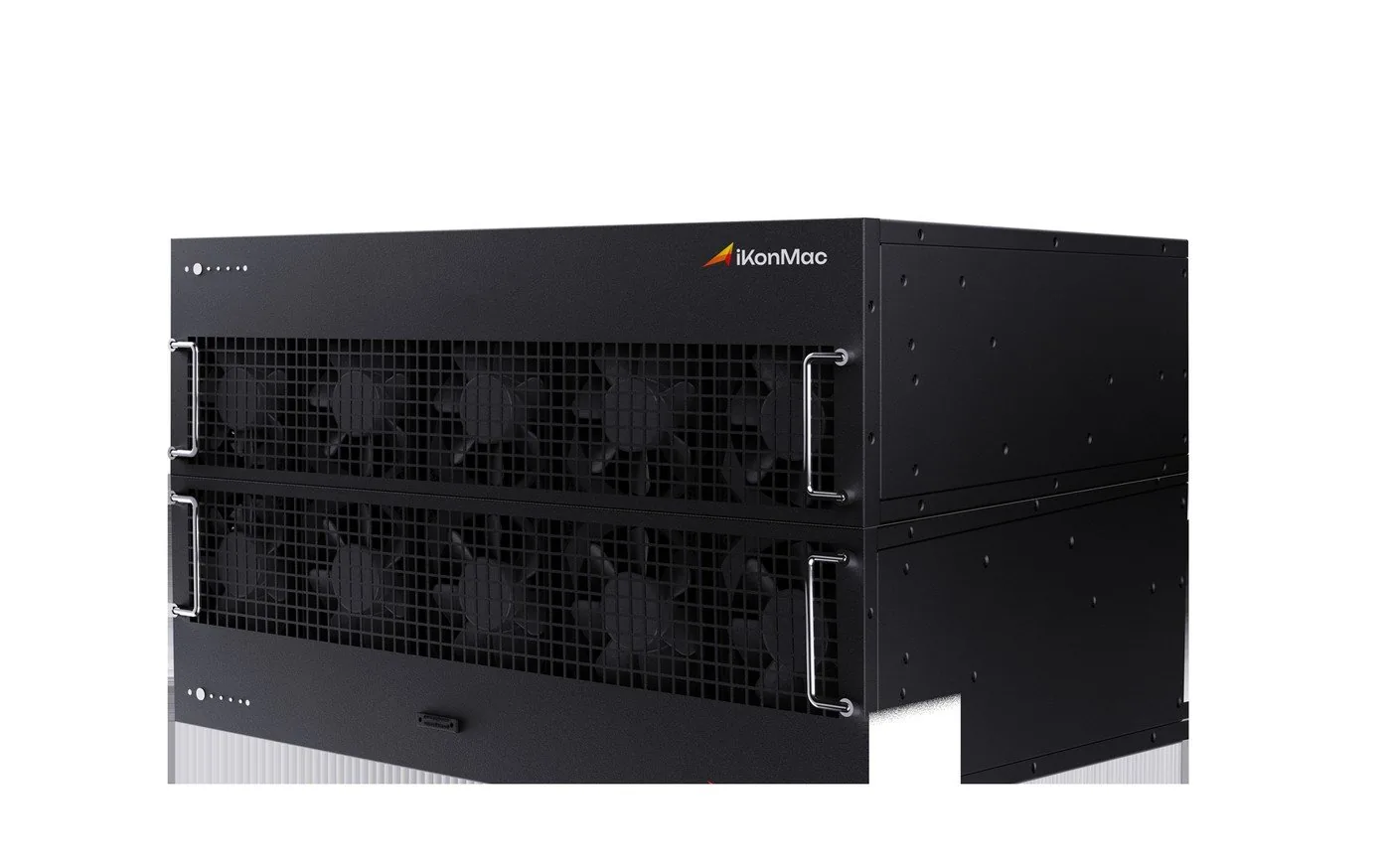
Thermal Isolation Protocol: Dual-zone internal airflow baffles completely isolate the SiC power semiconductor heatsink channel from sensitive digital control electronics, preventing conductive particle accumulation and premature thermal stress in demanding industrial environments.
Real-Time Processing Architecture & Fieldbus Protocols
The digital control engine combines dual 32-bit floating-point digital signal processors (DSP) with a high-speed field programmable gate array (FPGA). This architecture executes adaptive harmonic extraction, sliding-mode filtering algorithms, and real-time instantaneous reactive power theory (p-q theory) calculations within sub-microsecond control loops.
| Control Element | Implementation Details | System Capabilities |
|---|---|---|
| Processing Core | Dual 32-Bit DSP + High-Speed FPGA Array | Instantaneous parallel harmonic decomposition and PWM generation |
| Industrial Protocols | Modbus RTU (RS485) & Modbus TCP/IP (RJ45) | Direct integration into plant SCADA, DCS, and building BMS |
| Substation Automation | IEC 61850 Native Communication | Direct connection to digital substation automation switchgear |
| Local Touch HMI | 7-Inch / 10-Inch Color Graphical Touchscreen | Real-time waveform oscillograms, FFT spectra, and alarm logs |
| Module Interconnection | High-Speed Redundant CANbus Ring | Microsecond synchronization across parallelized drawer units |
| Cloud Telemetry | Ethernet RJ45 / Optional Industrial 4G Gateway | Encrypted remote diagnostics, health tracking, and firmware updates |
Automation & Monitoring Capabilities
- ✓ Waveform & Event Logging: Stores up to 10,000 timestamped disturbance logs and transient voltage/current captures for grid audit forensics.
- ✓ Multilingual User Interface: Configurable access profiles with password tiers for commissioning field technicians and plant operators.
- ✓ Autonomous Health Diagnostics: Continuous hardware monitoring evaluates DC-link capacitor health, gate driver states, and fan speeds before faults occur.
Need Native CAD / BIM Library Models for Switchgear Layouts?
iKonMac provides 3D STEP mechanical models, AutoCAD dimensional drawings, and Revit BIM blocks directly from our engineering team to accelerate your switchgear layout and panel fabrication schedule.
How to Prepare a Technical RFQ for SiC Power Quality Equipment
Specifying wide bandgap Silicon Carbide (SiC) power quality hardware requires establishing clear, verified electrical and environmental baselines. Unlike traditional silicon IGBT inverters that operate at conservative carrier frequencies between 10 kHz and 15 kHz, third-generation SiC MOSFET topologies operate with hard-switching frequencies from 30 kHz to 60 kHz. This high-frequency envelope enables selective active harmonic filter performance through the 50th order while reducing total thermal loss profiles below 1.2%.
Accurate front-end engineering input prevents costly module oversizing, simplifies HVAC thermal integration, and supports seamless compliance with IEEE 519-2022 standards. The iKonMac engineering team utilizes advanced ETAP, PSCAD, and MATLAB Simulink modeling platforms to cross-validate site-specific parameters before manufacturing. Follow the four-stage technical framework below to prepare a robust equipment RFQ.
Grid Topology and Nominal Voltage Parameters
Identify the primary electrical distribution characteristics at the Point of Common Coupling (PCC) or downstream switchboard. While SiC power converters provide superior transient ride-through capabilities, precise topological baseline data is necessary to size internal DC-link film capacitors and configure inductive LCL output stages.
- Nominal Bus Voltage & Swing: Define nominal operational voltage (e.g., 400V, 480V, or 690V AC) alongside sustained operational tolerance bands (standard ±15%, extreme ±20%).
- System Frequency & Stability: Document fundamental supply frequency (50 Hz or 60 Hz) along with dynamic deviation margins (±5%), especially when islanded or backed by emergency diesel generator sets.
- Transformer Capacity & %Z Impedance: State upstream distribution transformer kVA/MVA capacity, primary/secondary winding configurations, and short-circuit impedance percentage (%Z).
- Phase & Earthing Scheme: Clarify whether the distribution network is Three-Phase Three-Wire (3P3W) or Three-Phase Four-Wire (3P4W), and define earthing regimes (TN-S, TN-C, TT, or IT).
Harmonic Spectrum and Dynamic Reactive Demand
Compile power quality audit logs recorded via Class A power quality analyzers compliant with IEC 61000-4-30. SiC architecture enables wide-spectrum active mitigation, allowing simultaneous harmonic elimination, rapid reactive power stabilization, and load phase balancing.
- Dominant Harmonic Spectrum: Quantify discrete harmonic current amplitudes (RMS amperes) from the 2nd through the 50th order, highlighting typical 5th, 7th, 11th, and 13th non-linear loads.
- Target Distortion Levels: Note baseline Total Harmonic Current Distortion (THDi) and specify target limits at the PCC, typically targeted below 3% to 5% to comply with IEEE 519-2022.
- Reactive Compensation Envelope: Record baseline inductive and capacitive displacement power factor (cos φ) and determine the total dynamic kvar support needed for reactive power compensation to achieve ≥ 0.99.
- Dynamic Load Variation Rate: Outline the rate of load fluctuation (e.g., servo presses, arc furnaces, spot welders) to evaluate sub-millisecond dynamic response speed requirements.
Physical Footprint and Thermal Dissipation Bounds
Silicon Carbide active modules deliver exceptional volumetric power density reaching 3.2 kW per liter, reducing switchgear footprint by 30% to 50% compared to traditional IGBT cubicles. Defining physical and environmental boundaries supports accurate layout planning.
- Switchgear Space & Cable Entry: Measure maximum permissible cabinet dimensions (width × depth × height) and confirm whether top or bottom cable access is required.
- Ambient Thermal Rating: Detail electrical room ambient temperature ranges; iKonMac SiC hardware operates without derating up to 45°C and functions reliably up to 55°C.
- Enclosure Ingress Protection: Specify protection ratings according to ambient particulate conditions: standard IP20, or sealed IP31, IP42, and heavy industrial IP54 solutions.
- Acoustic Thresholds: Confirm noise criteria; high-frequency SiC switching pushes carrier harmonics beyond the human auditory spectrum, keeping operating noise < 52 dB(A).
Functional Scope, Redundancy, and Communications
Establish operational modes, hardware redundancy requirements, and integration pathways with supervisory facility networks. A modular architecture provides field scalability, allowing users to expand compensation capacity alongside future facility expansions.
- Compensation Priority Setup: Set allocation priorities across active harmonic mitigation, power factor compensation, and three-phase current imbalance balancing.
- Modular N+1 Redundancy: Specify hot-swappable sub-rack configurations to maintain continuous online conditioning during scheduled drawer maintenance.
- SCADA & Substation Telemetry: Indicate protocol requirements, including Modbus RTU (RS485), Modbus TCP/IP (Ethernet), CANbus, or power utility IEC 61850 compliance.
- Operator Interface (HMI): Select centralized 7-inch or 10-inch color touchscreen displays featuring event datalogging, waveform capture, and remote cloud analytics.
Technical Sizing Matrix: Silicon IGBT vs. SiC MOSFET Architecture
Key operational parameters affecting equipment sizing, thermal balance, and RFP specification
| Specification Parameter | Standard Silicon IGBT | iKonMac SiC Platform | Procurement & Sizing Impact |
|---|---|---|---|
| Switching Carrier Frequency | 10 kHz to 15 kHz | 30 kHz to 60 kHz | Mitigates up to the 50th harmonic order |
| Full-Load Thermal Dissipation | 2.5% to 2.8% of capacity | ≤ 1.2% total losses | Reduces HVAC cooling load by >40% |
| Volumetric Power Density | 1.8 kW per Liter | 3.2 kW per Liter | Reduces cabinet footprint by 30% to 50% |
| Dynamic Full-Step Response | < 5.0 ms | < 1.5 ms closed-loop | Rapid suppression of transient voltage sags |
| Acoustic Noise Generation | < 65 dB(A) audible hum | < 52 dB(A) whisper-quiet | Permissible inside cleanrooms & laboratories |
System Sizing and Network Interface Schematic
The schematic below details integration boundaries across facility medium/low-voltage distribution transformers, non-linear harmonic pollution loads, and iKonMac modular SiC compensation cubicles.

Figure 1.0: Interface boundaries for current transformer (CT) orientation, parallel drawer internal busbars, and centralized control telemetry.
Engineering RFQ Checklist
Key technical parameters for equipment sizing
On-Site Power Quality Audits
Lacking dynamic waveform recordings or harmonic distortion logs? Request certified power quality diagnostic services from iKonMac. Our application engineers deploy calibrated Class A analyzers to log voltage events, resonance points, and harmonic spectrums.
Engineering RFQ Documentation
Download our standard technical checklists and sizing spreadsheets to simplify specification and procurement reviews.
30 Years of Power Electronics Manufacturing Experience
Operating from our advanced manufacturing center in Pudong, Shanghai, iKonMac delivers over 3.5 million Amperes and kvar in power quality hardware annually. We combine verified industrial production capacity with exhaustive third-party type-test records to support electrical stability for mission-critical grids worldwide.
Founded in 1994
Three decades of specialized engineering across power electronic topologies, active harmonic filtering, and dynamic VAR compensation.
Dedicated R&D Engineers
Specialized engineering faculty featuring PhD, Postdoctoral, and Master-level specialists dedicated to SiC driver architecture and digital controls.
Exported to Over 50 Countries
Established international compliance and distribution network supporting industrial power installations across major global regions.
Industrial Partners
Long-term deployments across semiconductor cleanrooms, automated automotive plants, chemical complexes, and hyperscale data centers.
Pudong High-Tech Manufacturing Center
Our purpose-built facility integrates precision surface-mount assembly, vacuum pressure impregnation, and climate-controlled full-load burn-in bays to support uncompromising power semiconductor reliability.

International Certification & Compliance Matrix
Verified testing documentation and accredited third-party validation provide project owners and consulting engineers with complete support for overseas deployments.
Quality and Environmental Management
VerifiedCertified under ISO 9001:2015 and ISO 14001:2015 quality standards. Structured traceability tracks every batch from incoming bare silicon through mechanical cabinet integration.
European Conformity Directives
CompliantEngineered and verified in strict accordance with the CE Low Voltage Directive (LVD 2014/35/EU) and Electromagnetic Compatibility Directive (EMC 2014/30/EU) for direct EU grid connection.
Independent CNAS Type-Test Verification
AccreditedCertified laboratory type-test records certifying dynamic harmonic mitigation efficiency, continuous short-circuit withstand capability, and steady-state thermal behavior under full rating.
Ready to Modernize Your Industrial Power Quality with SiC Technology?
Direct Engineering Support Channels
- @ Technical Sales & RFQ Inquiries sales@ikonmacglobal.com
- # Global Hotline & WhatsApp Desk +86 176-2152-9866
- HQ Manufacturing HQ & Testing Center Building 1, East Area, 1st Floor, No. 508 Chuanhong Road, Pudong New Area, Shanghai, China