
Industrial Power Factor Correction (PFC) Solutions
Eliminate utility surcharge penalties, reclaim critical transformer capacity, and stabilize plant power factor above 0.99. Engineered by iKonMac with advanced reactive power compensation and sub-cycle dynamic response for mission-critical industrial networks.
The Compounded Cost of Low Power Factor — Utility Penalties and Distribution Bottlenecks
Operating industrial distribution infrastructure under an uncorrected lagging power factor creates continuous financial drain and electrical stress. Inductive loads—including three-phase induction motors, welding equipment, power transformers, and variable frequency drive rectifiers—draw non-working magnetizing reactive power (kvar) directly from the electrical grid. When left without dedicated reactive power compensation on-site, this circulating reactive current inflates overall apparent power (kVA), triggers aggressive utility billing surcharges, overheats switchgear conductors, and consumes valuable substation transformer headroom needed for production expansion.
Utility Penalty Surcharges and Peak kVA Demand Charges
Electric utilities establish mandatory power factor thresholds, typically requiring industrial accounts to maintain a minimum monthly average between 0.90 and 0.95 lagging. Falling below these mandated benchmarks triggers severe financial surcharges billed directly through monthly adjustment multipliers and elevated kVA peak demand structures.
- · Billing Tariff Multipliers: Contractual rate penalties compounded across total active energy consumption (kWh).
- · kVA Ratchet Liabilities: Brief reactive demand spikes locked into baseline billing for up to 12 consecutive months.
- · Unrecoverable OpEx Waste: Capital paid entirely for distribution system congestion with zero manufacturing output.
Transformer Capacity Saturation and Excessive I²R Line Heating
Total amperage drawn across main service feeders is inversely proportional to system power factor. Low operating power factor forces upstream substations, switchboards, and distribution cables to carry substantial circulating magnetizing current, leading to excessive thermal stress and premature equipment aging.
- · Capacity Bottlenecks: Up to 35% of nameplate transformer kVA consumed strictly by non-productive reactive flow.
- · Thermal Degradation: Continuous core and winding heating accelerates transformer dielectric oil breakdown.
- · Resistive Cable Losses: Increased I²R dissipation generates parasitic heat in bus ducts and underground feeder runs.
Bus Voltage Fluctuations, Severe Sags, and Nuisance Tripping
Excessive inductive reactive current passing through upstream line reactance generates substantial voltage drop across distribution switchgear. Sudden dynamic load swings—such as direct-on-line motor starts or stamping press duty cycles—induce deep bus voltage dips that disrupt sensitive digital controls unless mitigated with dynamic systems like a high-voltage SVG.
- · Automation Faults: Severe bus voltage drops trip sensitive PLCs, servo controllers, and variable speed drives.
- · Motor Torque Loss: AC induction motor output torque diminishes with the square of the applied supply voltage.
- · Process Interruption: Unscheduled automated line shutdowns routinely cost far more than turnkey PFC systems.
Technical Mechanics of Inductive Phase Lag and Apparent Power Demand
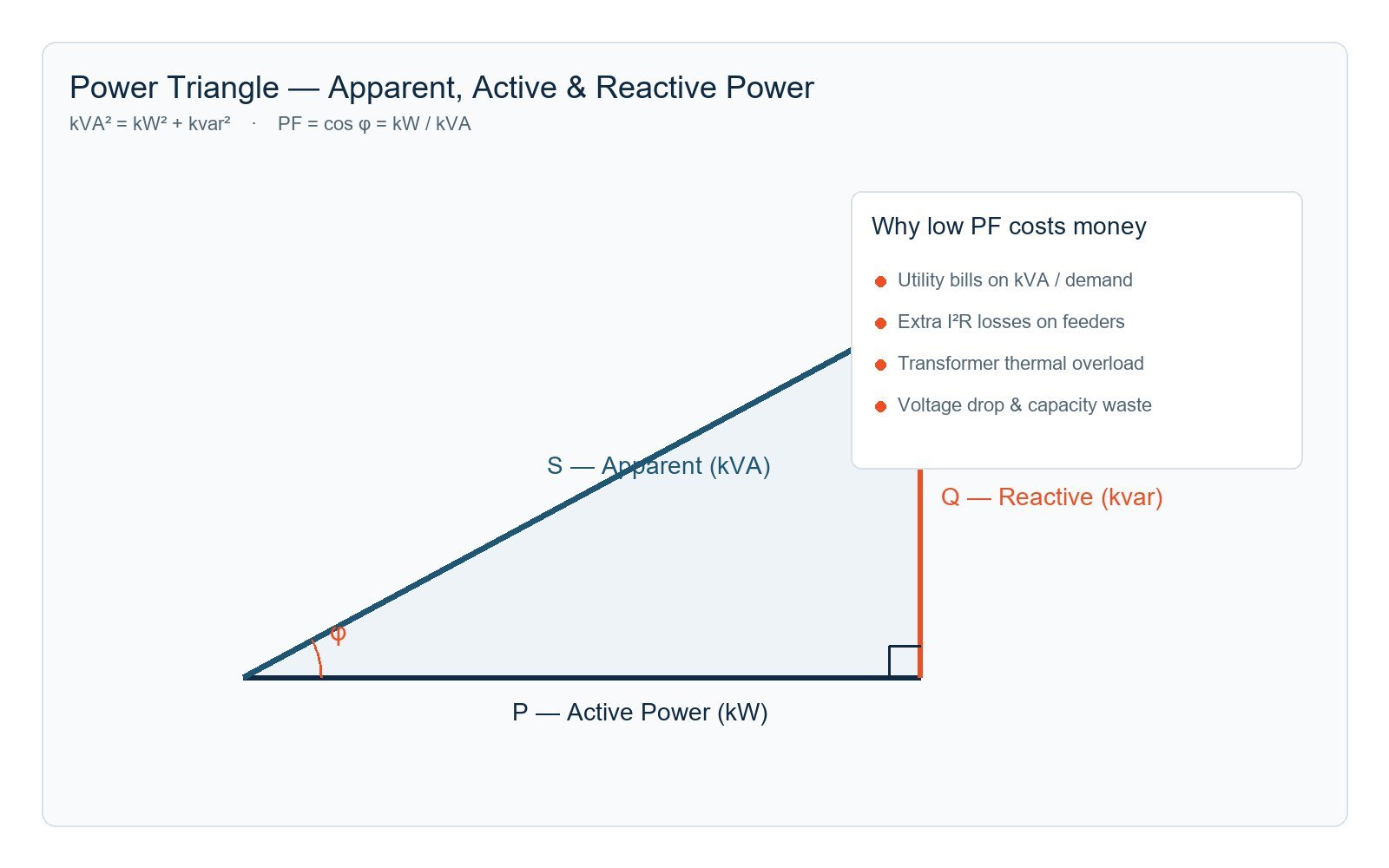
In alternating current (AC) power systems, inductive electromagnetic equipment shifts the current waveform out of phase, causing it to lag behind the supply voltage by a phase angle (θ). The cosine of this displacement angle (cos θ) defines the fundamental displacement power factor.
Total apparent power (S, measured in kVA) represents the vector summation of active working power (P, measured in kW) and magnetizing reactive power (Q, measured in kvar). When an industrial plant operates at an uncorrected power factor of 0.75, the electrical utility and plant substations must supply 1,333 kVA of total capacity simply to deliver 1,000 kW of mechanical output to the factory floor.
Data-Driven PFC Diagnosis — From Field Measurement to Dimensioning
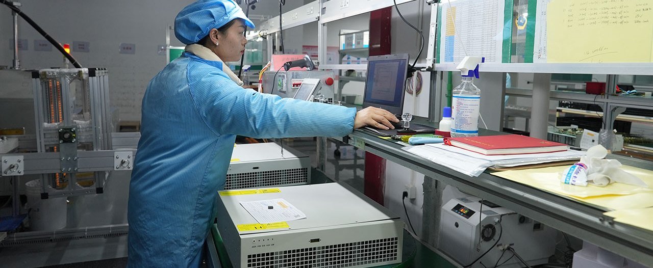
iKonMac eliminates sizing guesswork through certified Class-A electrical logging, load profile analytics, and harmonic resonance evaluations before recommending compensation hardware.
Continuous Seven-Day Logging & Dynamic Profile Analytics
Intermittent impact loads, cycling compressors, and non-linear drives distort standard utility billing meters. Our high-speed loggers record true active, reactive, and apparent power across complete production shifts to map exact kvar demand boundaries.
Captures peak production, off-shift idle states, and sudden start-up inrush transients.
Sub-cycle sampling precision for true displacement PF and total power factor calculation.
Harmonic Spectrum & Impedance Risk Analysis
Evaluating THD-u, THD-i, and transformer short-circuit impedance to prevent parallel harmonic resonance before applying capacitor banks or active compensation stages.
Structured Four-Stage Diagnostic & Dimensioning Process
From high-resolution data capture to single-line integration, turning site telemetry into verified performance.
Load Characterization
Record continuous real (kW) and reactive (kvar) trends, motor start surges, and rapid load cycling across production shifts.
Resonance Modeling
Model facility network impedance to calculate resonance points, detuning reactor ratios, or active harmonic filter integration needs.
Precision Sizing
Calculate net capacitive and inductive kvar demand to support a continuous target power factor of 0.99 without leading PF risks.
Engineering Delivery
Deliver verified Single Line Diagrams (SLD), equipment BOM, penalty elimination projections, and turnkey installation roadmaps.
Authoritative Diagnostic Reports for Engineering and Financial Teams
Every iKonMac power quality evaluation correlates raw telemetry against your utility tariff structure, quantifying transformer thermal relief, line loss mitigation, and monthly penalty elimination before equipment procurement.
Schedule a certified field recording or submit existing power logger data and utility bills for a professional dimensioning analysis.
Static Var Generators vs. Traditional Capacitor Banks for Industrial PFC
Modern industrial power distribution networks are dominated by non-linear loads, variable frequency drives (VFDs), automated welding lines, and power-conversion systems. Conventional mechanical capacitor banks—designed decades ago for steady-state, linear inductive loads—frequently fail in these environments due to harmonic resonance, contactor welding, and stepped over-compensation. Active Static Var Generator (SVG) technology represents a transformative shift in dynamic power factor correction beyond traditional static var compensator architectures, utilizing high-frequency IGBT inverters to deliver stepless, sub-cycle reactive compensation with continuous precision.
Engineering Comparison: Modern SVG vs. Legacy Capacitor Banks
Applicable to 400V / 480V / 690V Industrial Grids| Performance Parameter | Traditional Capacitor Bank | Detuned Capacitor Bank (7%/14%) | iKonMac Active SVG Solution |
|---|---|---|---|
| Dynamic Response Time | 30 to 180 seconds (Discharge timer delay) | 20 to 60 seconds (Thermal & discharge wait) | < 5 milliseconds (Instantaneous closed-loop response) |
| Compensation Granularity | Coarse stepped switching (25 / 50 kvar stages) | Fixed discrete steps; leads to hunting or under-compensation | Stepless, continuous linear regulation from 0 to 100% |
| Low-Voltage Output Behavior | Output drops by $V^2$ (51% capacity loss at 0.7 Un) | Reactive output degrades quadratically with bus voltage | Controlled current source: 100% rated current output during sags |
| Harmonic Interaction | High risk of parallel resonance & catastrophic failure | Avoids resonance at specific tuned frequency only | Resonance-immune; actively mitigates low-order harmonics |
| Directional Var Capability | Inductive lag only (Unidirectional capacitive output) | Inductive lag only (Unidirectional capacitive output) | Full 4-quadrant bi-directional tuning (-1.00 to +1.00 PF) |
| Target Power Factor Stability | Fluctuates widely (0.82 – 0.93 under fluctuating loads) | Step-dependent variance (0.86 – 0.94 under dynamic duty) | Target PF precisely stabilized at > 0.99 under all conditions |
| Maintenance & Lifecycle | 2–4 years; high contactor wear and dielectric drying | 3–5 years; elevated reactor heat and fan failures | 100,000 hours MTBF; solid-state IGBT reliability |
Sub-5ms Response vs. Sluggish Electromechanical Switching
Electromechanical contactors mandate mandatory internal discharge times (30 to 180 seconds) before re-energization to prevent dangerous inrush transients and contact welding. Rapidly cycling loads—such as metal stamping presses, automated resistance welders, injection molders, and overhead cranes—cycle far faster than contactors can engage.
iKonMac Static Var Generators leverage high-speed digital signal processors (DSP) and intelligent IGBT switching up to 20 kHz. The system continuously tracks load changes and outputs real-time corrective reactive current in under 5 milliseconds, eliminating power factor surcharge intervals on utility billing meters.
Constant-Current Output vs. Voltage-Square Degradation
Passive capacitor output is inherently tied to bus voltage: delivered reactive compensation collapses exponentially with the square of voltage drop ($Q = 2pi f C V^2$). During heavy motor start-ups, grid sags, or sudden transformer load surges where reactive support is most urgently required, conventional capacitors deliver their lowest compensation capacity.
Active SVGs function as controlled current sources rather than voltage-dependent impedances. An SVG maintains 100% rated reactive current output even when bus voltage sags down to 70% of nominal voltage, actively stabilizing bus voltage across medium and high voltage SVG deployments and preventing undervoltage trips on downstream drives and automation equipment.
Resonance Immunity & Simultaneous Harmonic Mitigation
Standard capacitor banks interact with upstream transformer leakage reactance to form parallel resonant circuits. Harmonic currents generated by non-linear loads (5th, 7th, 11th orders from rectifiers and VFDs) excite this resonance point, magnifying current distortion, causing fuse blowouts, and destroying dielectric layers.
Static Var Generators contain no passive LC circuits and cannot form resonant loops with the grid. In addition to dynamic power factor correction, iKonMac SVGs can dedicate spare inverter capacity or integrate with an active harmonic filter to eliminate dominant low-order harmonic currents, ensuring IEEE 519 compliance without needing separate detuning reactors.
Bi-Directional Four-Quadrant Operation
Conventional capacitor systems only supply capacitive (leading) reactive current to correct inductive (lagging) motors. In modern facilities with extensive underground cabling, server power supplies, or light weekend loading, the system may present a capacitive leading power factor, causing severe bus overvoltage and generator tripping.
Advanced SVG inverter architecture enables seamless, instantaneous transitions between capacitive and inductive reactive compensation across full 4-quadrant operations (-1.00 to +1.00 PF). This bi-directional capability supports dependable voltage regulation for data centers, solar plants, and regenerative braking drives.
Zero Step Hunting, Inrush Transients, and Mechanical Wear
Automatic capacitor controllers often encounter "hunting" behavior, repeatedly cycling physical contactors on and off when reactive demand falls between fixed step increments. This mechanical cycling generates damaging voltage transients, sparks contactor contacts, and causes premature capacitor can swelling.
Because SVG compensation is 100% solid-state and stepless, it dynamically injects the exact reactive current required down to fractions of a kilovar. With zero moving electromechanical parts, the system generates zero switching inrush surges and eliminates ongoing contactor maintenance costs.
High Power Density & Compact Retrofit Footprint
Traditional detuned capacitor banks rely on heavy iron-core tuning reactors and bulky oil/dry capacitor banks, requiring expansive multi-door enclosures, reinforced flooring, and intensive HVAC cooling to manage high thermal dissipation inside electrical rooms.
iKonMac active power electronics provide up to 300% higher power density. Modular rack-mount and wall-mounted SVG units can be integrated directly into existing switchgear lineups or compact standalone cabinets, saving valuable electrical room footprint and streamlining plant retrofits.
Upgrading from Legacy Capacitor Banks to Active SVG Technology
Industrial and commercial facilities confronting repeated capacitor failures, resonance issues, or persistent low power factor utility surcharges achieve immediate stability by retrofitting with active SVG systems. Transitioning to active power electronics permanently eliminates power factor penalties, optimizes transformer loading, and provides lifetime maintenance savings.
- Zero inrush transients and switching surges
- Sub-5ms closed-loop dynamic response speed
- Guaranteed stable power factor > 0.99
- Over 100,000-hour solid-state MTBF reliability
Engineered Hardware for Complete Power Factor Optimization
Eliminate utility surcharge penalties, stabilize bus voltage, and protect downstream equipment with iKonMac’s purpose-built power electronics hardware portfolio, engineered for low-voltage switchboards and high-voltage grid interconnections.
Static Var Generator (SVG)
Low-voltage rack-mount and wall-mount modules for 400V/690V networks, delivering sub-5ms bidirectional, step-less reactive compensation for fast-cycling loads.
High Voltage SVG
Direct-grid medium and high-voltage SVG systems for 6kV, 10kV, and 35kV substations, heavy metallurgy, arc furnaces, and utility-scale renewables.
Active Harmonic Filters
Advanced active harmonic filter and Ultra AHF solutions that neutralize 2nd to 50th order harmonics while supplying dynamic fundamental VARs to maintain a target 0.99 PF.
Silicon Carbide Power Modules
Next-generation silicon carbide power electronics delivering higher switching frequencies, minimal thermal losses, and ultra-high power density enclosures.
High-Volume Production Capacity with Stringent Quality Control
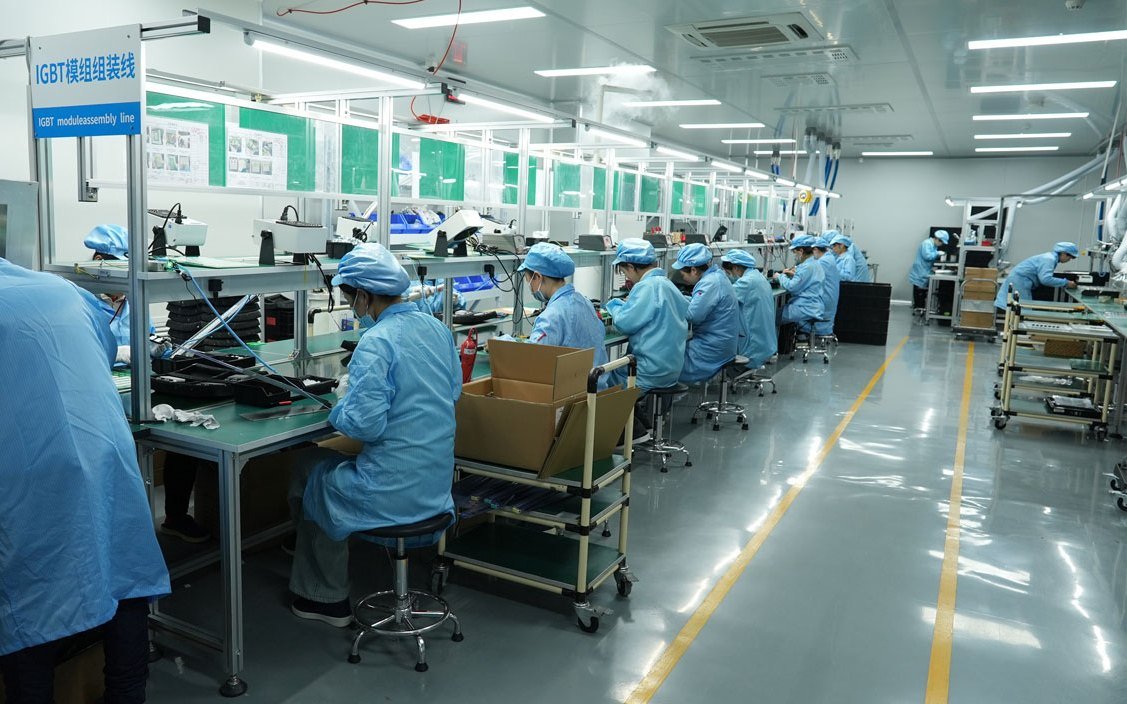
Every iKonMac reactive power compensation unit is engineered in ISO-certified facilities and undergoes 100% full-load burn-in testing before dispatch. Backed by 30+ years of power electronics expertise, our equipment provides dependable compensation across more than 50 countries.
Implementation from Engineering Topology to Commissioning
iKonMac executes turnkey power factor correction systems from initial single-line analysis through site energization. Our engineering discipline harmonizes physical siting, secondary control logic, and closed-loop testing to support target displacement power factor above 0.99 without grid resonance.
Multi-Tier Compensation Siting Strategy
Determining the correct point of connection balances capital expenditure, internal feeder losses, and utility billing penalty mitigation across facility networks.
Centralized Main Busbar
Installed directly on main low-voltage switchgear busbars. Delivers consolidated reactive power compensation to eliminate utility power factor surcharges across diverse operational loads.
- Lowest capital expenditure per kvar of compensation
- Supports >0.99 PF compliance at utility revenue meters
- Reclaims main transformer kVA reserve capacity
Group Sub-Distribution
Connected at Motor Control Centers (MCCs) and dedicated production distribution boards. Supplies dynamic reactive power locally to high-density inductive clusters.
- Compensates multiple variable-load motors simultaneously
- Curbs I²R thermal losses along extended feeder runs
- Permits isolated zone servicing without total plant shutdown
Point-of-Load Compensation
Hardwired directly at large inductive equipment terminals, such as chillers, crushers, and continuous induction furnaces, providing instantaneous magnetizing current on site.
- Fully unloads upstream branch cables and breaker switchgear
- Mitigates inrush-induced terminal voltage drops
- Operates interlocked with prime mover start/stop contactors
Secondary Control Integration & Anti-Hunting Automation
When pairing Active Harmonic Filters (AHF) with Static Var Compensator systems or legacy detuned banks, synchronized control schemes are critical to prevent control hunting and harmonic over-amplification.
Engineered CT Placement & Vector Alignment
Rigorous line-side vs. load-side current transformer configurations preserve closed-loop stability, preventing phase angle inversion and erroneous polarity measurement.
Zero Control Hunting Algorithms
Master-slave digital signal processing prioritizes reactive power delivery while delegating harmonic suppression, eliminating closed-loop hunting between parallel compensation modules.
Industrial Fieldbus & Telemetry
Native Modbus TCP/RTU, Profibus, and IEC 61850 integrations broadcast kvar output, power factor status, THD, and internal diagnostics directly to plant SCADA and EMS systems.

Structured Commissioning Milestones & Handover
Our field engineering division executes strict commissioning validation sequences, securing trouble-free energization and documented power quality improvement.
Phase & Polarity Validation
Detailed phase sequence verification, CT polarity confirmation, and primary ratio matching before system energization protect against phase mismatch faults.
Open-Loop Load Profiling
High-resolution recording of baseline apparent power (kVA), displacement power factor, and background voltage distortion under uncompensated operating cycles.
Closed-Loop Dynamic Tuning
Target power factor setpoint lock (0.98–1.00), stepped compensation response testing, and verification of instantaneous step-load tracking without over-compensation.
Handover & Personnel Training
Formal delivery of verified before-and-after performance logs, electrical commissioning certificates, and complete on-site HMI and maintenance staff training.
Comprehensive Engineering Support for EPCs & Integration Teams
From bid evaluation to final energization, iKonMac partners directly with consulting engineers, EPC general contractors, and electrical panel builders to de-risk delivery.
SLD Review & kvar Sizing Calculations
Rapid single-line diagram reviews, reactive capacity calculations, and transformer loading assessments provide rock-solid project submittal foundations.
BIM Models & Enclosure Integration
Detailed 3D Revit models, CAD enclosure dimensional layouts, and thermal dissipation guidelines accelerate switchroom planning and conduit routing.
Factory Engineers & Field Verification
Experienced application engineers supervise secondary control wiring, parameter initialization, and performance testing for guaranteed sign-off.
Need Single-Line Diagram Review or PFC Sizing Support?
Submit your SLD or utility billing profile to receive technical sizing within 24 hours.
Performance Validation — Measurable Economic Payback and Grid Impact
Industrial power factor correction turns non-productive reactive current into immediate operational cash flow. Sustaining a steady 0.99 power factor eliminates utility billing surcharges, reclaims thermal headroom across existing transformers, and lowers peak kVA demand charges across industrial distribution networks.
Heavy inductive lag incurring monthly billing surcharges and poor feeder efficiency.
Utility power factor adjustment penalty levied under standard industrial tariffs.
Excess reactive current limits expansion room and accelerates thermal degradation.
Motor starts and cyclic dynamic loads induce terminal voltage drops and drive trips.
Quantifiable Payback Mechanics and Surcharge Elimination
Operating industrial facilities without dynamic reactive power compensation generates persistent economic losses. When uncorrected inductive loads—including induction motors, chillers, electric arc furnaces, and variable frequency drive front-ends—draw magnetizing current from the grid, utility meters register lagging displacement power factor. To recover transmission losses and feeder congestion, electric utilities levy compound billing surcharges whenever monthly averages slip below mandated thresholds (typically 0.90 to 0.95).
iKonMac Static Var Generator (SVG) systems counteract this financial drain instantaneously. By synthesizing precise, opposing capacitive or inductive current at sub-cycle speeds (less than 5 milliseconds), the system dynamically locks overall plant power factor at a continuous 0.99. This eliminates tariff penalties entirely, unlocks potential power factor rebate incentives, and trims measured peak kVA billing demand.
Capital Amortization Factors
- 1 100% Penalty Elimination: Eradicates recurrent low power factor surcharges starting from the initial billing cycle following commissioning.
- 2 Peak kVA Demand Trimming: Minimizing apparent power draw curtails monthly billing demand charges by 12% to 20% on capacity-billed tariffs.
- 3 Internal I²R Copper Loss Mitigation: Removing circulation of idle reactive amperes cools cables, decreases switchgear operating temperatures, and trims kWh technical losses.
- 4 Substation Capital Deferral: Liberating 15% to 25% of existing transformer kVA allows plant production expansion without multimillion-dollar substation upgrades.
Typical Investment Payback Model
Representative audited performance figures derived from an operational manufacturing plant operating a 2,000 kVA substation service:
Stringent Factory Acceptance Testing and Documented Field Commissioning
iKonMac enforces strict quality assurance protocols, combining factory acceptance power quality testing (FAT) with certified on-site power quality audits compliant with IEEE 519 and IEC 61000 standards.
| Verification Stage | Standard Protocol | Acceptance Benchmark | Client Deliverable |
|---|---|---|---|
| Pre-Shipment FAT | Full-capacity thermal burn-in, dielectric isolation, and harmonic immunity checks | 100% rated kvar dynamic injection at <50 dB(A) acoustic profile | Certified Factory Acceptance Test Report |
| On-Site Commissioning | CT polarity confirmation, phase-lock loop synchronization, and step-load transient response | Full reactive response achieved in <5ms without transient hunting | Closed-Loop Commissioning Sign-Off Record |
| 30-Day Grid Audit | Continuous high-resolution logging of true PF, displacement PF, THDu, and kVA demand | Steady displacement PF ≥ 0.99 sustained throughout full duty cycles | Documented Utility Savings Verification Dossier |

Continuous Verification Support
Every iKonMac installation includes comprehensive telemetry logging and monitoring capabilities to continuously verify power factor target attainment and audit ongoing financial payback.
Industry-Tailored Power Factor Correction Applications
From high-voltage arc furnaces to hyperscale cleanrooms, iKonMac delivers purpose-engineered reactive power compensation that eliminates utility penalties, stabilizes bus voltage, and prevents costly harmonic resonance.
Active Static Var Generation for High-Impact Loads
Modern industrial automation combines rapid cycling with non-linear distortion. Legacy electromechanical capacitor banks switch on multisecond delays, frequently overcompensating or triggering catastrophic LC resonance. Our inverter-grade SVG systems respond within milliseconds to preserve unity power factor.
<5 ms Response Time
IGBT-switched compensation tracks sudden load surges in less than a quarter-cycle.
Zero Resonance Risk
Acts as a controlled current source, preventing harmonic amplification with the grid.
Bidirectional Output
Continuously corrects lagging inductive and leading capacitive loads across all quadrants.
Full Rated Voltage Support
Maintains full rated reactive current output even during severe utility voltage sags.

Engineered Systems for Demanding Sector Demands
Review how iKonMac tailors hardware topologies, switching speeds, and protection ratings to the distinctive load dynamics of your industry.
Dynamic Voltage Stabilization for Electric Arc Furnaces and Steel Mills
Scrap meltdown and rolling mill impacts drive severe sub-cycle reactive swings, heavy interharmonics, and severe phase unbalance that exceed utility flicker thresholds.
Ultra-Fast Resonance-Free Compensation for Semiconductor Cleanrooms
Sensitive photolithography tools and etching clusters require absolute voltage stability, where traditional capacitor banks risk dangerous harmonic resonance.
Bi-Directional Reactive Power Management for Lightly Loaded Data Centers
Lightly loaded server power supplies and extensive cable charging create a leading power factor, destabilizing backup generators and causing utility surcharges.
Grid Code Compliance and Nighttime Reactive Support for Solar and Wind Plants
Interconnection codes mandate stringent power factor windows at the point of interconnection (POI), even when renewable generation drops to zero after dusk.
Harsh Environment Ingress Protection for Petrochemical and Process Drives
Continuous motor-driven pumps and compressors degrade plant power factor, while ambient airborne sulfur, chemical dust, and heat corrode sensitive control electronics.
Transformer Capacity Optimization for Healthcare and Commercial Facilities
Heavy diagnostic imaging loads and HVAC chiller cycling cause peak kVA demand spikes, thermal overloading, and utility penalties on shared commercial distribution networks.
Application-Specific Compensation Topology Matrix
Compare key design parameters and targeted compensation topologies across major industrial applications.
| Application Domain | Primary Electrical Challenge | Recommended iKonMac Hardware | Response Latency | Regulatory Standard |
|---|---|---|---|---|
| Steel Mills & Arc Furnaces | Voltage flicker, rapid reactive surges, phase imbalance | High Voltage SVG / Medium-Voltage STATCOM | <5 milliseconds | IEEE 1453 / IEEE 519 |
| Semiconductor Cleanrooms | Harmonic resonance risk, sensitive tool voltage sags | Rack-Mounted Low-Voltage SVG + AHF Modules | <5 milliseconds | SEMI F47 / IEEE 519 |
| Hyperscale Data Centers | Leading power factor, UPS filter capacitance | Bi-Directional 4-Quadrant Static Var Generator | <5 milliseconds | EN 50600 / IEEE 1100 |
| Solar & Wind Sub-Stations | Point of interconnection compliance, Q@Night VAR demand | Substation High Voltage SVG (6 kV – 35 kV) | <10 milliseconds | IEEE 2800 / FERC Order 827 |
| Petrochemical Refineries | Continuous VFD inductive loads, corrosive atmospheres | NEMA 4X / IP54 Enclosed Dynamic SVG Systems | <5 milliseconds | ISA-71.04 Class G3 |
| Hospitals & Commercial Real Estate | Transformer kVA overloading, chiller peak demand | Modular Low-Voltage Static Var Generator | <10 milliseconds | NFPA 99 / ASHRAE 90.1 |
Eliminate Power Factor Penalties with Engineered Precision
Send us your electrical single-line diagram (SLD) or recent utility bills. Our power quality specialists will calculate required kvar capacity and projected ROI within 24 hours.
Frequently Asked Questions on Power Factor Correction
Modern industrial distribution networks operate under demanding conditions driven by non-linear inductive loads, variable frequency drives, and strict utility billing tariffs. Below, iKonMac application engineers address critical technical considerations, architectural decisions, resonance risks, and lifecycle realities across industrial power factor correction (PFC) systems.
Have Specific Distribution Challenges?

Field Diagnostics & Harmonic Testing
Proper equipment dimensioning requires empirical logging to distinguish displacement reactive demand from harmonic distortion. Prevent resonance disasters through certified pre-installation audits.
iKonMac Power Electronics Architecture. Compliant with international grid codes, ANSI/IEEE 519, and IEC 61921 standards.
Stop Paying Utility Penalties. Optimize Your Power Factor Today.
Three-Step Engineering Assessment Protocol
Utility Billing & Penalty Surcharge Audit
Single-Line Diagram (SLD) & Resonance Analysis
Optimized System Sizing & Global Delivery Plan

Backed by three decades of power electronics manufacturing, iKonMac delivers turnkey low-voltage and medium-voltage compensation systems across 50+ countries.
Request a PFC Assessment
Speak directly with an iKonMac power systems engineer. Submit your facility profile below for a detailed sizing review.