
Power Quality Engineering: End-to-End Systems from Measured Baseline to Grid Connection
Proven Engineering Scale & Power Quality Solutions
iKonMac backs global EPC contractors and mission-critical facilities with industrial-grade active harmonic filter mitigation, dynamic var compensation, and end-to-end grid compliance from front-end design to site commissioning.
Founded in 1994, pioneering power electronics innovation and high-reliability turnkey electrical system design.
Active filtering and dynamic static var compensator solutions manufactured annually for complex utility and industrial loads.
Worldwide deployments engineered in full compliance with IEEE 519, IEC 61000, and ANSI grid connection codes.
The trusted power quality partner for EPC general contractors, design institutes, and tier-one plant operators.
Power Quality Engineering Workflow — From Field Measurement to Grid Interconnection
Delivering compliant electrical distribution systems demands a structured transition from empirical on-site waveform capture to verified grid handover. iKonMac executes an integrated five-stage power quality engineering workflow engineered for EPC contractors, design consultants, and industrial plant engineers across our power quality products. Every phase pairs rigorous field diagnostic inputs with deterministic design deliverables, ensuring absolute compliance with IEEE 519-2022 and IEC 61000 grid interconnection standards across complex, high-order harmonic environments.
Closed-Loop System Design for Stringent Grid Codes
Our multi-disciplinary methodology eliminates brownfield integration risks, mitigates hazardous parallel resonance conditions, and supports total accountability from sub-cycle waveform capture to formal on-site commissioning and utility sign-off.
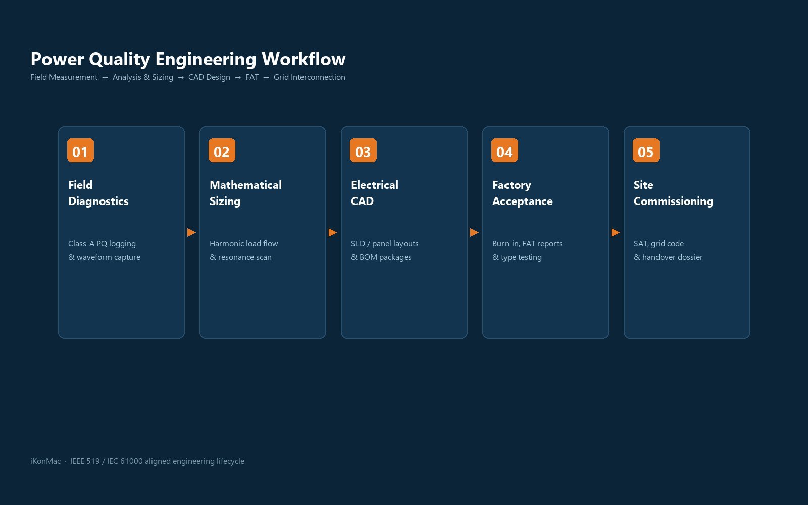
Stage 1: Field Diagnostics, Harmonic Logging, and Baseline Profiling
Phase Boundary: Diagnostic AcquisitionThe power quality system design process starts with high-resolution field logging at the Point of Common Coupling (PCC) and high-impact non-linear load branches. Using Class A power quality analyzers, iKonMac engineers quantify background harmonic distortion, dynamic load cycling, and point-of-installation impedances to establish an uncompromised mathematical baseline for filtering and reactive compensation.
- · Grid background total harmonic voltage distortion (THDv) spectrum up to the 50th order
- · Branch load harmonic current distortion (THDi), neutral current, and phase unbalance vectors
- · Peak inductive/capacitive reactive step rates (kvar/s) and prospective short-circuit ratio (Isc/IL)
- · Comprehensive Power Quality Diagnostic Audit and Waveform Analysis Dossier
- · Dynamic Reactive Demand Profile and Duty Cycle Operating Envelope Report
- · PCC Baseline Compliance Gap Assessment referencing IEEE 519 and IEC 61000-2-4
Stage 2: Mathematical Sizing, Anti-Resonance Modeling, and Topology Selection
Phase Boundary: Analytical CalculationSenior power systems engineers import logged field data into harmonic power flow models to calculate optimal sizing margins and prevent destructive electrical resonance. We evaluate system fault levels, upstream transformer impedances, and downstream power factor bank interactions to configure the ideal electrical layout—whether centralized static var compensator networks, localized point-of-load filtering, or a multi-level hybrid architecture.
- · Transformer nameplate parameters (kVA rating, %Z impedance, X/R ratio, and vector group)
- · Operational coincidence factors, future facility expansion plans, and motor starting inrush profiles
- · Installed capacitor banks, detuning reactor percentages, and distribution cable capacitances
- · Active Harmonic Filter (AHF) and Static Var Generator (SVG) Mathematical Capacity Calculations
- · Impedance Frequency Sweep Curves and Parallel Resonance Mitigation Validation Report
- · Topology Comparison Study (Centralized Busbar vs. Decentralized Branch Architecture)
Stage 3: Electrical CAD Schematics, Protection Integration, and BOM Design
Phase Boundary: Detailed Design EngineeringTheoretical sizing is translated into actionable manufacturing blueprints and construction documentation. Our engineering team develops primary electrical single-line diagrams, secondary control interconnects, current transformer sizing schedules, structural panel layouts, and forced-air or liquid cooling thermal designs to support seamless physical integration into industrial electrical rooms.
- · Substation footprint, cable trench coordinates, top/bottom entry constraints, and ambient thermal limits
- · Main busbar short-circuit withstand ratings (kA/1s), upstream breaker trip curves, and relay settings
- · Plant automation protocols and telemetry interface requirements (Modbus RTU/TCP, Profibus, IEC 61850)
- · Primary Electrical Single-Line Diagrams (SLD) and Substation Integration Drawings in CAD DWG/PDF
- · Secondary Control Schematics, CT Polarity Schedules, and Terminal Interconnection Wiring Plans
- · Complete Engineered Bill of Materials (BOM), Cable Sizing Schedules, and Thermal Load Dissipation Plans
Stage 4: Factory Acceptance Testing (FAT), Hardware Stress Burn-In, and System Interlocking
Phase Boundary: Factory Quality VerificationPrior to site delivery, all AHF power modules, SVG inverter racks, and master-slave centralized controllers undergo rigorous factory validation at our primary manufacturing facility. Testing protocols include continuous full-load heat-run burn-in, dielectric isolation verification, electromagnetic immunity evaluations, and multi-cabinet high-speed communication stress testing under emulated non-linear load conditions.
- · Approved engineering submittal drawings and protective trip setting coordination schedules
- · Client SCADA communications register map, baud rates, and hardware address assignments
- · Project-specific FAT procedure requirements, witness testing criteria, and quality inspection hold points
- · Certified Factory Acceptance Test (FAT) Protocol Report and Full-Load Thermal Imaging Logs
- · Dielectric Insulation Resistance and Hi-Pot Voltage Withstand Test Certification
- · Multi-Module Master-Slave Coordination Simulation Sign-Off and Pre-Shipment Inspection Record
Stage 5: On-Site Commissioning, SAT Grid Interconnection, and Technical Handover
Phase Boundary: Utility Interconnection & Operational HandoveriKonMac field service engineers oversee installation verification, primary CT vector polarity checks, and dynamic parameter tuning under live facility operating cycles. We validate closed-loop harmonic attenuation, sub-5ms reactive response, and stepless power factor stabilization against contractual IEEE 519 targets before completing formal operations and maintenance training for plant personnel.
- · Cabinet mechanical landing sign-off, torque audit records, and auxiliary power readiness
- · External current transformer wiring continuity, phase association, and polarity orientation checks
- · Plant operational schedule for incremental stage energization across representative load cycles
- · Site Acceptance Testing (SAT) Sign-Off Certificate and Closed-Loop Performance Attenuation Log
- · Formal IEEE 519-2022 and IEC 61000 Grid Code Compliance Verification Dossier
- · Complete As-Built Operation and Maintenance Manuals, Recommended Spares List, and Training Records
Power Quality Engineering Execution Matrix
This project execution framework outlines engineering scopes, governing technical standards, and contractual milestones across every stage of power quality system implementation.
| Implementation Phase | Core Technical Focus | Governing Engineering Standard | Milestone Project Deliverable |
|---|---|---|---|
| 01. Baseline Profiling | Class A diagnostic spectrum logging, background THDv/THDi capture, and dynamic load cycling analysis | IEC 61000-4-30 Class A / IEEE 1159 | Power Quality Site Diagnostic Audit Dossier |
| 02. Mathematical Sizing | Harmonic current allocation, dynamic reactive compensation sizing, and impedance resonance sweep modeling | IEEE 519-2022 / IEC 61000-3-6 | System Sizing and Anti-Resonance Calculation Report |
| 03. CAD & Schematic Design | Primary single-line diagrams, secondary control interconnects, CT schedules, and thermal cooling design | ANSI / NEMA / IEC 61439-1/2 | Issued-for-Construction (IFC) CAD DWG Drawing Package |
| 04. Integrated FAT Validation | Full-power thermal burn-in, dielectric withstand verification, and multi-cabinet master-slave communication testing | ISO 9001 / IEC 62477-1 | Certified Factory Acceptance Test (FAT) Sign-Off Protocol |
| 05. Site Commissioning (SAT) | On-site parameter tuning, CT polarity verification, closed-loop harmonic attenuation, and operational training | Regional Utility Interconnection Codes | Final Site Acceptance Testing (SAT) Compliance Dossier |
End-to-End Engineering Accountability and OEM Support
Backed by 30+ years of dedicated power electronics research and manufacturing since 1994, iKonMac application engineers support mathematical simulations and field designs translate into flawless harmonic mitigation and power factor stabilization across the most demanding industrial facilities.
Distribution Topologies and Mathematical Sizing Methodology
Industrial electrical networks require rigorous parametric sizing and impedance profiling prior to equipment selection. Choosing among point-of-load mitigation, centralized substation compensation, and multi-level hybrid architectures dictates dynamic filtering performance, CAPEX efficiency, and long-term grid reliability. Backed by three decades of power electronics engineering, iKonMac applies harmonic load flow calculations and harmonic impedance frequency sweeps to eliminate current distortion without risking network resonance.
Simulated Harmonic Assessment
iKonMac performs detailed digital network simulation to model harmonic impedance profiles, preventing parallel resonance between upstream transformer leakage inductance and downstream power factor capacitors.
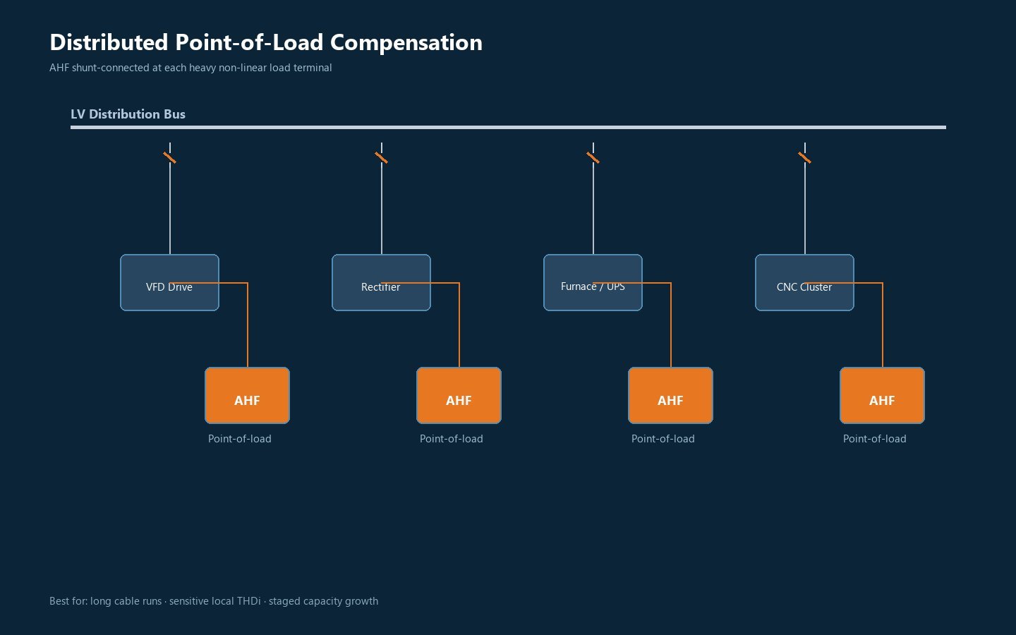
Distributed Point-of-Load Compensation
System Architecture & Operation
Advanced active harmonic filter (AHF) units connect directly in parallel with high-capacity non-linear loads, such as multi-pulse variable frequency drives, thyristor rectifiers, and induction heating equipment. Harmonic currents are neutralized directly at their point of generation, preventing distorted currents from circulating through internal plant distribution cables, bus ducts, and upstream supply transformers.
Application Criteria
- · High-Capacity Drives: Individual VFD or converter loads rated above 250 kW.
- · Extended Cable Runs: Feeder runs exceeding 100 meters where harmonic voltage drops create bus distortion.
- · Sensitive Branch Loads: Metrology sensors, PLC I/O racks, or laboratory systems co-located on adjacent sub-panels.
Mathematical Sizing Algorithm
Sizing incorporates a 1.20 to 1.30 safety factor over calculated harmonic RMS current, providing necessary thermal headroom to manage dynamic load step changes and high crest-factor waveforms.
When implementing point-of-load compensation across long cable runs, calculate cable capacitance against upstream transformer leakage reactance. iKonMac embeds programmable virtual damping algorithms within the AHF firmware to prevent high-frequency LC resonance between converter switching frequencies and cable impedance.
Topology Selection and Sizing Specification Matrix
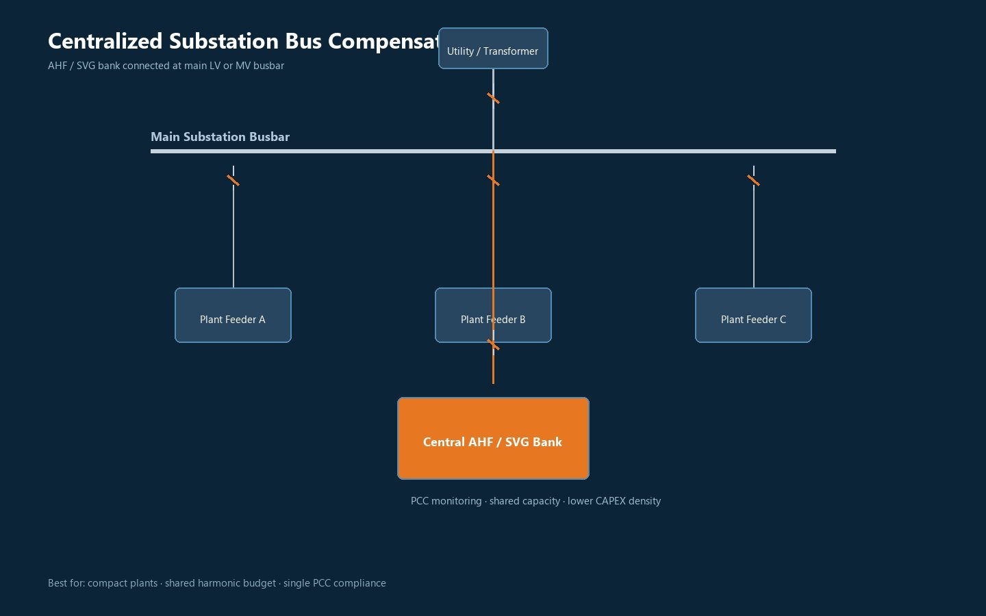
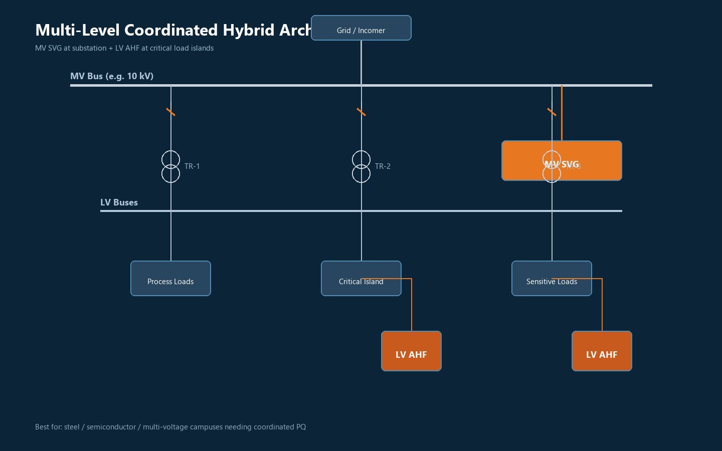
Evaluating the trade-offs between point-of-load, centralized substation, and multi-level hybrid topologies is essential when planning electrical distribution. The comparison matrix below outlines core design factors, resonance risk factors, and recommended applications.
| Engineering Parameter | Distributed Point-of-Load | Centralized Substation Bus | Multi-Level Hybrid Network |
|---|---|---|---|
| Point of Connection | Dedicated non-linear drive or furnace terminals | Secondary 400V/690V main switchboard busbar | Primary MV incoming busbar plus LV branch sub-panels |
| Distribution Line Losses | Minimized (Harmonics neutralized at source) | Moderate (Feeder cables conduct harmonic currents) | Optimized (Clean sinusoidal flow across all distribution tiers) |
| Sizing Calculation Factor | 1.20 to 1.30 of peak THDi current | 0.75 to 0.85 diversity-scaled aggregate demand | Independent MV dynamic reactive & LV harmonic sizing |
| Relative CAPEX Profile | Higher (Multiple distributed enclosures) | Lowest (Consolidated modular rack enclosures) | Engineered for large-scale utility and heavy industrial installations |
| Parallel Resonance Risk | Low (Direct compensation at load feeder) | Elevated if legacy capacitor banks remain active | Negligible (Active closed-loop virtual damping across tiers) |
| Primary Industry Fit | Heavy VFD drives >250kW, pump stations, kilns | Commercial infrastructure, HVAC, automated assembly | Steel production, solar PV farms, semiconductor cleanrooms |
Harmonic Resonance Prevention Protocols
Parallel electrical resonance occurs when system inductive reactance matches the capacitive reactance of existing capacitor banks or long cable runs at a specific harmonic frequency:
If this resonant frequency aligns with characteristic 5th, 7th, 11th, or 13th harmonic orders, current amplification can trigger capacitor failures, nuisance breaker tripping, and severe transformer overheating.
- ✓ Detuned Reactor Application: Integrate 7% or 14% series detuned reactors to shift resonant points well below dominant 5th harmonic frequencies.
- ✓ Active Virtual Damping: iKonMac AHF firmware applies selective anti-phase compensation to actively damp system resonance loops.
- ✓ Static Var Generator Retrofits: Replace stepped LC capacitor banks with stepless static var compensator technology to eliminate parallel LC resonant circuits completely.
Capacity Margin Rules for Dynamic Industrial Profiles
Standard root-mean-square calculations frequently undersize equipment when applied to dynamic, fast-cycling industrial loads. to support reliable continuous operation, apply structured derating factors during the initial sizing phase:
All iKonMac low-voltage systems use modular, hot-swappable power modules, allowing EPCs and plant operators to size initial capacity precisely while maintaining simple plug-and-play expansion options for future facility growth.
Request an Engineering Sizing and Resonance Review
Submit your single-line diagram (SLD) and load schedule. iKonMac application engineers will model your distribution network, calculate resonance margins, and deliver a detailed equipment bill of materials within 48 hours.
AHF and SVG Dynamic Coordination Control & Hybrid Mitigation
Eliminate control hunting, phase displacement errors, and inter-unit hunting with iKonMac master-slave algorithmic coordination. Our hybrid power quality system unifies active harmonic filter (AHF) and static var generator (SVG) units into a synchronized, single-bus mitigation architecture.
Engineering Bottlenecks in Disconnected Systems
Deploying standalone AHF and SVG units with independent sampling architectures creates systemic instability across variable industrial switchgear:
- · Phase Calculation Deviations
Dual independent instrument transformer (CT) loops introduce angular measurement drift, causing conflicting phase angle computations and reactive circulation currents between converters.
- · Dynamic Response Lag Disparities
Microsecond-level AHF processing operating parallel to slower, stepped compensation curves triggers transient hunting, transient overshoot, and bus voltage jitter during load switching.
- · Bus Oscillation Hunting
Independent current injection loops without centralized vector arbitration trigger continuous reactive cycling, shifting LC resonances into sensitive industrial control networks.
- · Uncoordinated Overcompensation Penalties
Simultaneous corrective injections cause transient leading power factors, inadvertent reverse VAR flows across the utility Point of Common Coupling (PCC), and thermal overloading of neutral lines.
Master-Slave Dynamic Allocation Engine
iKonMac proprietary centralized control arbitrates full-spectrum compensation demands across centralized and distributed hybrid topologies:
Unified Bus Sensing Architecture
A centralized controller samples network line currents through a dedicated, class 0.2S current transformer cluster, executing simultaneous Fast Fourier Transform (FFT) extraction of fundamental reactive demand and 2nd to 50th harmonic vectors.
Intelligent Dynamic Command Dispatch
Fundamental inductive and capacitive reactive currents are routed preferentially to lower-cost SVG and static var compensator modules, freeing high-speed AHF inverter bandwidth to neutralize complex harmonic orders and negative-sequence unbalance currents.
Sub-5ms Closed-Loop Synchronization
Direct microsecond-bus optical coupling supports full-spectrum mitigation within 5 milliseconds, dampening terminal voltage fluctuations across harsh dynamic loads such as electric arc furnaces, shredders, and crane hoists.
Engineering and Capital Payoffs
CAPEX Optimization of 20% to 35%
Reallocating bulk reactive compensation from costly active filter hardware to high-density SVG blocks cuts overall bill-of-materials equipment expenses without compromising total harmonic mitigation targets.
Zero Phase Hunting and Overcompensation
Deterministic current allocation eliminates multi-inverter hunting, preventing reverse VAR energy export, transformer saturation, and utility power factor demand penalties.
IEEE 519 Compliant Harmonic Suppression
Maintains current total harmonic distortion (THDi) consistently below 3% under nonlinear converter loading, protecting upstream transformers and sensitive instrumentation from harmonic heating.
Bi-Directional True Power Factor Stablization
Maintains steady-state operational power factor strictly above 0.99 through seamless, stepless inductive-to-capacitive reactive transitions across fluctuating production shifts.
Key Technical Differentiators
Microsecond Inter-Module Bus
Industrial CAN-FD and fiber-optic communication buses coordinate multi-cabinet IGBT switching patterns in real time, guaranteeing deterministic, jitter-free harmonic cancellation.
Selective Order Decomposition
Programmable harmonic rejection allows selective mitigation targeting specific trouble frequencies (e.g., 5th, 7th, 11th, and 13th) to maximize active filter headroom while suppressing resonance points.
Integrated Three-Phase Unbalance Correction
Simultaneous zero- and negative-sequence active injection balances asymmetrical phase loadings across individual phases, stabilizing neutral-to-ground potentials in four-wire networks.
Evaluating the sizing ratio between active filtering and dynamic VAR compensation, or sizing a high-voltage SVG for an upcoming facility? Consult our power systems engineering team for a comprehensive topology sizing review.
Engineered Equipment Array for Power Quality Infrastructure
Translate electrical single-line diagrams directly into utility-certified hardware. From modular low-voltage active filters to utility-scale SVG systems, iKonMac delivers complete power quality equipment arrays engineered in-house, without third-party dependency.
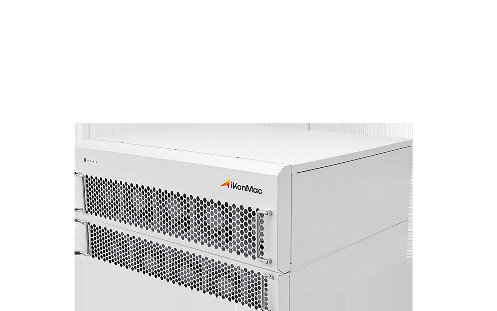
Active Harmonic Filter (AHF)
Precision targeted cancellation for high-order harmonic distortion from variable frequency drives, UPS systems, and industrial rectifiers. Each modular active harmonic filter supports rack-mount configurations and standalone IP54 floor cabinets.
Key Engineering Specifications
- Operating Voltage: 400V / 690V (±15%, 50/60 Hz)
- Filtration Range: 2nd to 50th Harmonic Order
- Response Speed: < 5 ms Full Compensation Time
- PCC Compliance: IEEE 519-2022 (THDi < 3%–5%)
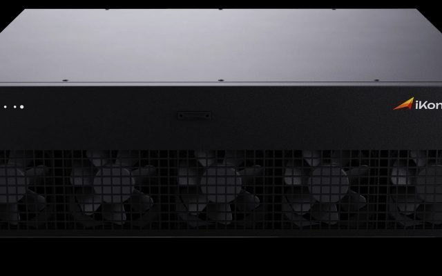
Static Var Generator (SVG)
Stepless bidirectional reactive power correction and dynamic unbalance mitigation. Replaces traditional stepped capacitor banks to eliminate resonance risks and reverse-power utility penalties.
Key Engineering Specifications
- Power Factor Output: Continuous -1.00 to +1.00 Range
- Phase Compensation: Independent 3-Phase Unbalance Tuning
- Grid Safety: Immune to LC Network Harmonic Resonance
- Dynamic Step Time: < 5 ms Full-Load Ramp

High Voltage SVG
Medium-voltage transmission and grid interconnect voltage stabilization. The utility-scale high voltage SVG is engineered for solar farms, wind power substations, and heavy electric arc furnace facilities.
Engineering Specifications
- Circuit Topology: H-Bridge Cascaded Chain-Link
- Capacity Rating: Scalable up to 100+ Mvar
- Fault Support: LVRT / HVRT Grid Code Compliant
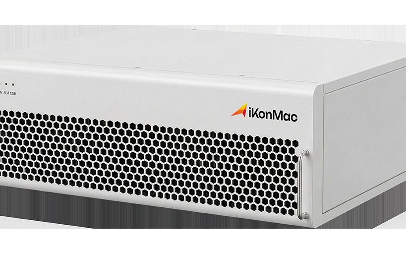
Ultra Active Harmonic Filter
Deploy our advanced ultra active harmonic filter for wideband distortion cancellation engineered specifically for semiconductor cleanrooms, hyperscale data centers, and medical diagnostic labs.
Engineering Specifications
- Carrier Switching: Ultra-High Frequency Bandwidth
- Interharmonics: Fractional & High-Order Filtering
- Bus THDv Level: Suppression Below 1.5% THDv
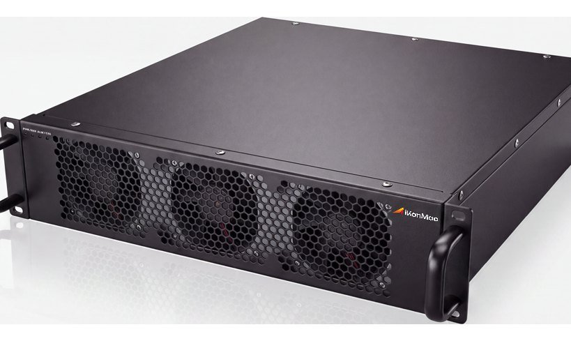
Silicon Carbide Power Electronics
Advanced wide-bandgap conversion modules delivering extreme power density, substantially reduced thermal dissipation, and ultra-compact physical enclosure footprints.
Engineering Specifications
- Power Device: Solid-State SiC MOSFET Inverter
- Thermal Losses: 30% Efficiency Improvement
- Cabinet Footprint: 40% Space Reduction
Direct-from-Manufacturer Engineering & Equipment Delivery
iKonMac engineers, builds, and tests all low-voltage modules and utility-scale systems under strict ISO 9001 quality controls, ensuring seamless interoperability across every industrial project.
Power Quality Protection Design and Industrial SCADA Integration
Mission-critical industrial networks demand deterministic fault clearance and uncompromised supervisory control. iKonMac engineers robust hardware protection topologies and native telecommunication protocols across its power quality products, ensuring uninterrupted active harmonic mitigation, continuous voltage stability, and transparent asset monitoring across plant-wide SCADA and energy management platforms.
Multi-Level Electrical Safety & Hardware Protection
Safeguarding high-speed IGBT inverter stages and dynamic compensation systems against grid disturbances requires coordinated, microsecond-level tripping sequences. iKonMac incorporates an autonomous multi-tier protection matrix spanning power semiconductor junctions, DC-link circuits, and line-side coupling hardware.
Inverter-Level Microsecond Isolation
Direct hardware desaturation detection executes gate-drive shutdowns during short-circuit and extreme overcurrent faults within under 10 microseconds. Comprehensive IGBT gate undervoltage monitoring, DC overvoltage clamping, and dynamic junction thermal throttling prevent catastrophic silicon breakdown during high di/dt events.
Grid-Level Dynamic Isolation & Surge Suppression
Adaptive control algorithms identify overvoltage, undervoltage, unbalance, and abnormal frequency drift (df/dt), initiating immediate soft de-energization during severe utility instability. Standard integrated Class II Surge Protective Devices (SPDs) clamp lightning impulses and high-energy switching transients across all phases and neutral conductors.
Current Transformer Auto-Shorting Diagnostics
Continuous current loop integrity sensing detects loose connections or secondary-side open circuits instantly. Automated internal shorting relays safely close the CT circuit within milliseconds, eliminating hazardous high-voltage arcing, fire risks, and measurement card failure during operational field maintenance.
Industrial Automation & SCADA Remote Dispatch
Plant distributed control systems (DCS), building management systems (BMS), and substation automation panels require direct, low-latency telemetry. iKonMac power quality solutions deliver unbridged, native communication stacks configured to meet rigorous international power automation standards.
Open Fieldbus & Industrial Ethernet Integration
Dual RJ45 Ethernet ports and galvanically isolated RS-485 interfaces deliver native compatibility with Modbus RTU, Modbus TCP, Profibus-DP, and Profinet. Standardized register mapping facilitates remote system staging, real-time power factor setpoint adjustment, and dynamic mode switching from central control rooms.
Substation Digital Automation via IEC 61850
Native IEC 61850 compliance enables clean integration into digital substation architectures without protocol converters. High-speed GOOSE messaging executes deterministic interlocking between upstream medium-voltage circuit breakers and power quality conditioning units without point-to-point copper wiring.
High-Speed Telemetry & Condition-Based Monitoring
Integrated digital signal processors capture full-cycle fault transient waveforms, harmonic spectrum distributions through the 50th order, and DC capacitor aging telemetry. High-resolution sequence-of-events (SOE) logs with 1 ms timestamping provide an actionable baseline for predictive asset maintenance.
Engineering Interface Specifications & Telemetry Mappings
Standardized signal mappings streamline front-end engineering design (FEED), accelerate EPC electrical drafting, and eliminate plant commissioning conflicts.
| Subsystem Interface | Standard Protocol / Signal | Telemetry and Control Scope | Isolation and Rating |
|---|---|---|---|
| Plant SCADA / EMS System | Modbus TCP / Profinet via Dual Redundant RJ45 | Three-phase V/I RMS, THDv/THDi, P/Q/S power flows, displacement PF, alarm matrices, remote fault reset | 2.5 kV Galvanic Isolation / Cat III 600V |
| Substation Automation System | IEC 61850 Edition 2 (MMS Client/Server & GOOSE) | Feeder interlock permissive, directional var dispatch, dynamic tripping coordination, 1 ms SOE logging | Optical Fiber (ST/LC) or Shielded Cat6A |
| Hardwired Safety & Control I/O | 24 VDC Optocoupled Inputs / Form-C Dry Relays | Remote Emergency Power Off (EPO), breaker auxiliary feedback, hardware interlock permissive, master trip | 3.75 kV Optocoupler Dielectric Isolation |
| Current Transformer Sensing | Class 0.2S / 0.5S Input (1A or 5A Secondary Loops) | Fundamental line/load currents, 2nd to 50th harmonic FFT extraction, zero-sequence imbalance tracking | Galvanic Isolation with Auto-Shorting Clamps |
Engineered for Extreme Industrial EMI Environments
Operating high-capacity active harmonic filter systems and static var generators alongside multi-megawatt variable frequency drives, induction arc furnaces, and thyristor converters introduces intense electromagnetic transients. iKonMac equipment incorporates internal Faraday shielding, physical low-voltage isolation, optical fiber gate synchronization, and full compliance with IEC 61000-6-2 and IEC 61000-6-4 industrial EMC standards to support deterministic command execution and continuous data integrity.
- Industrial EMC Category C3 / C2 Certified
- Fiber-Optic Inter-Module PWM Bus Sync
- Dual-Core Independent Hardware Watchdog
- Non-Volatile FRAM Fault Event Storage
EPC Engineering Deliverable Packages & International Compliance Standards
Eliminate design revisions, expedite consultant approvals, and pass utility audits on schedule. iKonMac equips EPC contractors with comprehensive, audit-ready engineering documentation packages compliant with IEEE, IEC, and regional grid code mandates.
Pre-formatted submittal packages structured to meet EPC technical schedules and tender requirements without RFI loop delays.
Certified PCC voltage and current distortion verification dossiers benchmarked against IEEE 519-2022 and IEC standards.
Standardized factory acceptance protocols, site commissioning workbooks, and stamped quality records ready for owner handover.
Engineering Drawings & Sizing Calculations
Comprehensive electrical single-line, civil loading, and physical enclosure integration designs engineered for seamless switchgear coordination.
- Schematic & Single-Line Diagrams (SLD)Native CAD and DWG layouts detailing power bus routing, CT polarities, interlocks, and protection interfaces.
- Switchgear Elevation & Mechanical LayoutsEnclosure dimensions, conduit entry cutouts, center-of-gravity calculations, and structural base anchoring plans.
- Harmonic Power Flow & Thermal CalculationsShort-circuit withstand ratings, resonance frequency sweeps, and cabinet heat dissipation data for active harmonic filter integration and HVAC sizing.
FAT, SAT & Quality Verification Records
Rigorous factory and site inspection protocols backed by accredited quality systems to support third-party and owner technical acceptance.
- Factory Acceptance Test (FAT) ProtocolsWitnessed testing logs covering full-load thermal burn-in, dynamic step response, and multi-unit communication failovers.
- Site Acceptance Test (SAT) ProceduresOn-site parameter commissioning templates, insulation tests, closed-loop harmonic verifications, and punch-list records.
- Accredited Third-Party Type Test ReportsLaboratory type test certificates under ISO 9001, ISO 14001, and ISO 45001 manufacturing quality standards.
Grid Interconnection & O&M Deliverables
Certified compliance statements for electrical utility interconnection filings alongside turnkey plant operational and maintenance manuals.
- IEEE 519-2022 Limit VerificationEngineering calculation statements proving total demand distortion (TDD) and THDv compliance under maximum short-circuit ratios for high-voltage SVG grid connections.
- IEC 61000 Measurement & Emission ReportsFormal compliance files addressing IEC 61000-4-30 Class A measurement methods and IEC 61000-3-6 planning level limits.
- Comprehensive Operation & Maintenance ManualsPreventative maintenance schedules, troubleshooting matrices, and recommended 2-year operational spare parts schedules.
Four-Stage Project Submittal & Milestone Matrix
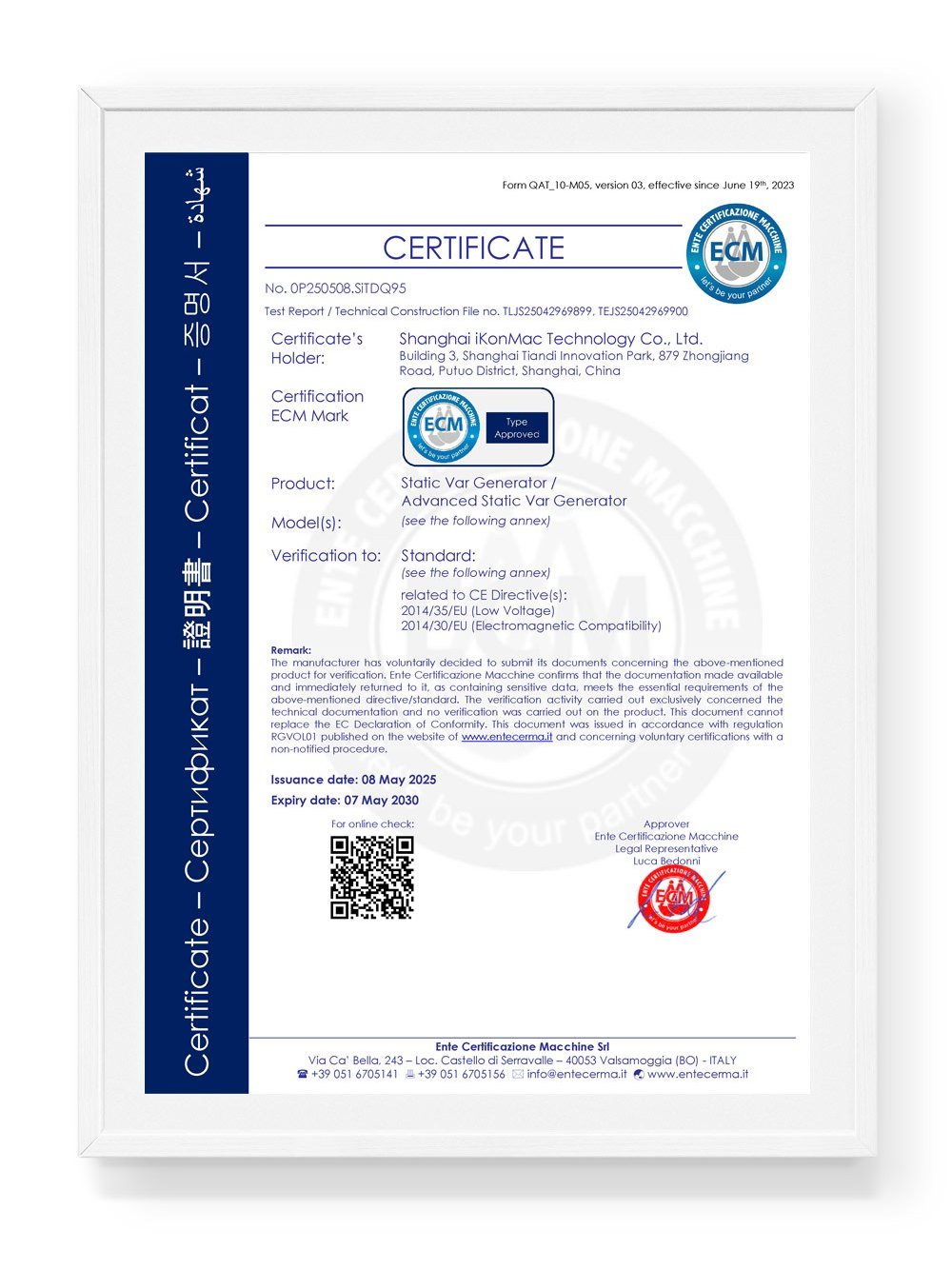
iKonMac engineering teams follow a disciplined submittal structure that mirrors global EPC project lifecycles. We deliver fully indexed documentation packages to supports continuous progress through design freezes and grid code audits.
Engineered Mitigation for Demanding Industrial Operating Environments
Modern industrial distribution networks face compounding electrical stresses from variable frequency drives, arc-producing loads, and high-density switched power supplies. Left unmanaged, severe harmonic pollution, dynamic reactive power swings, and phase imbalances cause unexpected breaker trips, transformer overheating, and costly utility non-compliance penalties. Backed by field execution across more than 3,000 industrial installations worldwide, iKonMac delivers tailored power quality system engineering calibrated to the distinct disturbance signatures of mission-critical facilities.
Semiconductor Cleanrooms
Extreme vulnerability to microsecond commutation notches, sub-cycle voltage sags, and high-frequency harmonics generated by photolithography equipment, ion implanters, and precision chiller drives.
Integration of Ultra Active Harmonic Filters with millisecond-grade dynamic var compensation, actively stabilizing bus voltage and suppressing total harmonic distortion below stringent semiconductor thresholds.
Steel Mills & Arc Furnaces
Violent cycle-by-cycle reactive power surges, severe short-term voltage flicker (Pst), negative-sequence phase unbalance, and heavy interharmonic spectrums produced during the furnace melting phase.
Medium-voltage High Voltage SVG architectures deployed at substation feeders for dynamic voltage support, combined with decentralized low-voltage AHF modules dedicated to auxiliary process drives.
Hyperscale Data Centers
Dense arrays of single-phase switched-mode power supplies producing excessive 3rd, 9th, and 15th zero-sequence triplen harmonics that superimpose on the neutral conductor, creating extreme thermal risks.
Dedicated three-phase four-wire active harmonic filter banks delivering point-of-load neutral compensation, eliminating circulating zero-sequence currents and reclaiming upstream transformer capacity.
Solar PV & Microgrids
High-frequency inverter switching interactions combined with low short-circuit ratios in weak grid connections, inducing harmonic resonance risks at the point of interconnection during high irradiance ramps.
Full grid-impedance sweep modeling paired with coordinated SVG systems providing automated Q@Night reactive power injection, power factor regulation, and bidirectional fault ride-through support.
Technical Matrix: Industrial Operating Environments vs. Mitigation Architecture
Determining the optimal system architecture requires precise correlation between spectral disturbance orders, load step speeds, and source impedance characteristics. The comparative engineering matrix below demonstrates how specific industrial load signatures govern equipment topology selection, response time requirements, and mandatory international compliance thresholds.
| Industrial Sector | Dominant Electrical Challenge | Critical Harmonic Orders | Dynamic Response Requirement | Engineered System Topology | Core Compliance Standard |
|---|---|---|---|---|---|
| Semiconductor Fabrication | Sub-cycle voltage notches & sensitive bus distortion | 11th, 13th, 23rd, 25th | < 5 milliseconds | Point-of-load Ultra AHF + Active Var Generation | SEMI F47, IEEE 519 (THDv < 1.5%) |
| Electric Arc Metallurgy | Severe flicker (Pst/Plt) & violent reactive shifts | 2nd, 3rd, 5th, even & interharmonics | < 10 milliseconds | Substation High Voltage SVG + Low-Voltage AHF | IEC 61000-3-7, IEEE 1453 (Pst < 0.8) |
| Hyperscale Data Centers | Zero-sequence triplen current on neutral conductor | 3rd, 9th, 15th, 21st | < 10 milliseconds | Three-phase four-wire AHF Neutral Mitigator | IEEE 519, TIA-942 (Neutral I < 5%) |
| Renewable PV & Microgrids | Weak grid resonance & nocturnal reactive demand | High-order switching frequency bands | < 20 milliseconds | Centralized Hybrid SVG with Q@Night Dispatch | IEEE 2800, Utility Interconnection Codes |
System Engineering Built on Rigorous Field Validation
Standard catalog power factor equipment and basic passive traps frequently fail in severe industrial settings due to thermal overload, LC parallel resonance, and unsynchronized control loops. iKonMac system engineering mitigates operational risk through pre-deployment frequency sweep analysis, hardware-in-the-loop firmware coordination, and high-margin thermal engineering before equipment leaves the factory floor.
- ✓ Anti-Resonance Impedance Modeling: Every engineering proposal includes harmonic resonance simulations to verify safe operation alongside existing capacitor banks, preventing catastrophic LC amplification.
- ✓ High Thermal and EMC Operating Margins: Advanced power electronics utilize optimized silicon carbide configurations, reinforced magnetic components, and intelligent thermal throttling for 50°C ambient operation.
- ✓ Complete Turnkey EPC Documentation: Engineering packages include comprehensive CAD single-line drawings, short-circuit calculations, relay protection settings, and documented FAT/SAT compliance certificates.
Review Your Single-Line Diagram with Senior Specialists
Whether upgrading brownfield distribution switchgear, resolving chronic data center neutral overheating, or ensuring substation compliance for grid-scale renewable generation, iKonMac application engineers deliver comprehensive sizing models and mitigation architectures tailored to your project.
Power Quality Engineering and Capacity Sizing Technical FAQ
Technical guidance on harmonic filter sizing, resonance mitigation, topology selection, and commissioning standards for industrial facilities and EPC electrical engineering projects.
Have a Complex Distribution Topology?
Submit your single-line diagrams (SLD) or harmonic measurement logs. iKonMac application engineers deliver capacity sizing calculations and anti-resonance assessments within 48 hours.
- IEEE 519 and IEC 61000 compliance modeling
- Complete Bill of Materials (BOM) sizing reports
- Direct consultation with power quality system architects
International Compliance Standards
All engineering deliverables adhere to ANSI/IEEE 519-2022 harmonic control limits, IEC 61000-4-30 Class A measurement standards, and regional grid interconnection codes across 50+ countries.
Initiate Engineering Project Consultation & SLD Review
Submit project single line diagrams, load schedules, or power quality measurement audits. iKonMac application engineers deliver comprehensive harmonic mitigation and reactive power compensation topology evaluations and precision equipment bill of materials.
Engineering Sizing Commitments
-
48-Hour Rapid SLA
Receive preliminary capacity calculations, target power factor correction models, and topology recommendations within 48 business hours.
-
IEEE 519 & IEC 61000 Compliance
Engineered CAD schematics and single line diagram integration designed directly to international grid-compliance benchmarks.
-
Senior Systems Specialist Access
Direct engagement with senior power electronics application specialists without intermediation by sales generalists.
Backed by iKonMac central manufacturing infrastructure and international project delivery execution for EPC contractors worldwide.
Direct Engineering Desks
Submit Project Specifications
Provide system parameters below to fast-track harmonic assessment, active filter configuration, and commercial quotation.